
Current Transformers
What are Current Transformers?
Current Transformers (CT) are electrical current transformers used to convert high currents in the main circuit into lower currents that can be measured by measuring instruments or protective relays. This allows for efficient and safe monitoring and control of electrical systems. The principle of operation is based on electromagnetic induction, where the current flowing through the primary winding in the main circuit creates a magnetic field proportional to the current. This magnetic field induces a current in the secondary winding connected to the measuring device. The current in the secondary winding has a reduced value relative to the current in the main circuit according to the transformation ratio of that particular Current Transformer.
Types of Current Transformers
- Wound Primary Current Transformers have primary windings with a specific number of turns, where the current flowing through the primary winding is the direct current to be measured.
- Bar-Type Current Transformers use busbars as primary windings and are suitable for high-current circuits.
- Window-Type Current Transformers have a central opening through which the main wire or busbar passes, making them easy to install.
- Split-Core Current Transformers have a magnetic core that can be separated, suitable for installation in circuits where operation cannot be interrupted.
Applications of Current Transformers
- Used to monitor and measure currents in electrical systems or power stations for maintenance and energy management in the energy industry.
- For protecting electrical systems, used with protective relays (Protective Relays) to prevent short circuits, leakage current, and control current in machinery and equipment in manufacturing industries.
- Control and analyze the quality of electricity - Used for analyzing the quality of electricity and improving the efficiency of electrical systems.
- Used to install and inspect electrical systems in buildings and construction projects in the construction industry.
- Used to monitor and analyze electrical systems in electric vehicles for the automotive industry.
Renowned Brands of Current Transformers
- ABB, a leading brand renowned for quality and reliability in electrical equipment.
- Eaton, a brand with high-quality products specializing in energy management.
- GE Grid Solutions, a brand specialized in manufacturing electrical equipment and managing power systems.
- KEPLER INSTRUMENTS, a brand with diverse high-quality products that are reliable.
- Schneider Electric, a brand with a wide range of products specializing in energy management.
- Siemens, a brand specialized in technology and innovation in electrical systems.
View Current Transformers Catalog : Click here
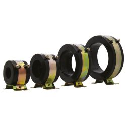 KCT-60R, 500/5A KEPLER Current TransformerSpecial Price THB 320.00 Regular Price THB 400.00
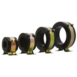 KCT-60R, 600/5A KEPLER Current TransformerSpecial Price THB 320.00 Regular Price THB 400.00
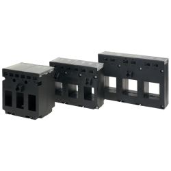 KCT-3P-35, 100/5A KEPLER Current TransformerSpecial Price THB 800.00 Regular Price THB 1,000.00
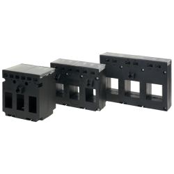 KCT-3P-45, 400/5A KEPLER Current TransformerSpecial Price THB 960.00 Regular Price THB 1,200.00
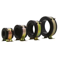 KCT-35R, 30/5A Kepler Current TransformerSpecial Price THB 320.00 Regular Price THB 400.00
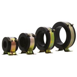 KCT-60R, 800/5A KEPLER Current TransformerSpecial Price THB 320.00 Regular Price THB 400.00
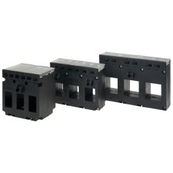 KCT-3P-35, 200/5A KEPLER Current TransformerSpecial Price THB 800.00 Regular Price THB 1,000.00
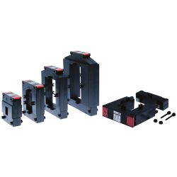 KCTS-23, 300/5A KEPLER Split Core Current TransformerSpecial Price THB 1,040.00 Regular Price THB 1,300.00
Delivery: 4 ก.ย. 2569
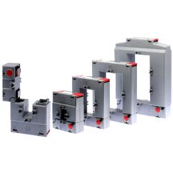 KCTP-816, 2500/5A KEPLER Split Core Current TransformerSpecial Price THB 3,840.00 Regular Price THB 4,800.00
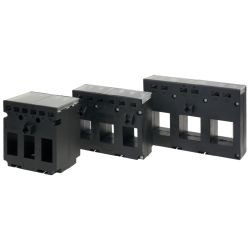 KCT-3P-45, 500/5A KEPLER Current TransformerSpecial Price THB 1,000.00 Regular Price THB 1,250.00
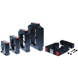 KCTS-58, 600/5A KEPLER Split Core Current TransformerSpecial Price THB 1,320.00 Regular Price THB 1,650.00
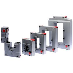 KCTP-58, 600/5A KEPLER Split Core Current TransformerSpecial Price THB 1,360.00 Regular Price THB 1,700.00
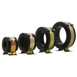 KCT-35R, 300/5A KEPLER Current TransformerSpecial Price THB 320.00 Regular Price THB 400.00
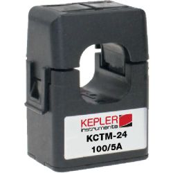 KCTM-24, 300/5A KEPLER Split Core Current TransformerSpecial Price THB 680.00 Regular Price THB 850.00
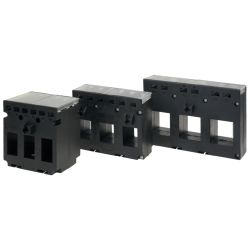 KCT-3P-45, 300/5A KEPLER Current TransformerSpecial Price THB 880.00 Regular Price THB 1,100.00
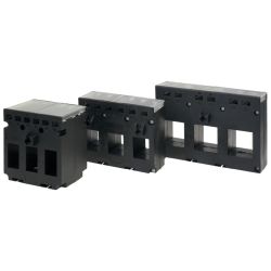 KCT-3P-45, 630/5A KEPLER Current TransformerSpecial Price THB 1,040.00 Regular Price THB 1,300.00
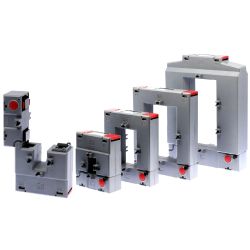 KCTP-816, 3000/5A KEPLER Split Core Current TransformerSpecial Price THB 4,000.00 Regular Price THB 5,000.00
 KCTC-50, 500/5A KEPLER Clamp-on Current TransformerSpecial Price THB 5,663.00 Regular Price THB 7,550.00
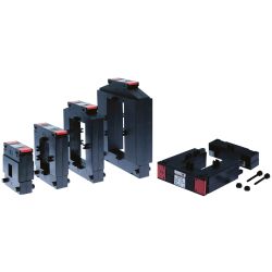 KCTS-23, 150/5A KEPLER Split Core Current TransformerSpecial Price THB 1,040.00 Regular Price THB 1,300.00
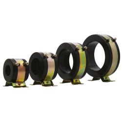 KCT-90R, 1000/5A KEPLER Current TransformerSpecial Price THB 400.00 Regular Price THB 500.00
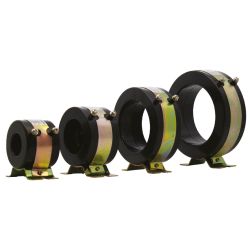 KCT-90R, 1200/5A KEPLER Current TransformerSpecial Price THB 400.00 Regular Price THB 500.00
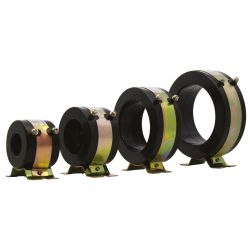 KCT-90R, 1500/5A KEPLER Current TransformerSpecial Price THB 480.00 Regular Price THB 600.00
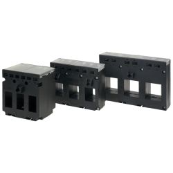 KCT-3P-35, 250/5A KEPLER Current TransformerSpecial Price THB 800.00 Regular Price THB 1,000.00
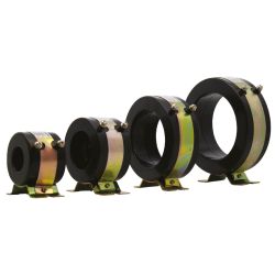 KCT-60R, 400/5A KEPLER Current TransformerSpecial Price THB 320.00 Regular Price THB 400.00
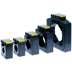 KCT-40, 100/5A KEPLER Current TransformerSpecial Price THB 240.00 Regular Price THB 300.00
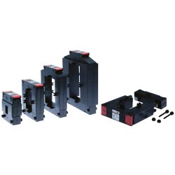 KCTS-23, 100/5A KEPLER Split Core Current TransformerSpecial Price THB 1,040.00 Regular Price THB 1,300.00
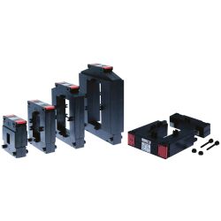 KCTS-812, 1500/5A KEPLER Split Core Current TransformerSpecial Price THB 2,000.00 Regular Price THB 2,500.00
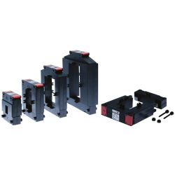 KCTS-58, 400/5A KEPLER Split Core Current TransformerSpecial Price THB 1,160.00 Regular Price THB 1,450.00
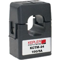 KCTM-24, 150/5A KEPLER Split Core Current TransformerSpecial Price THB 680.00 Regular Price THB 850.00
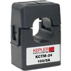 KCTM-24, 200/5A KEPLER Split Core Current TransformerSpecial Price THB 680.00 Regular Price THB 850.00
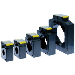 KCT-30, 50/5A KEPLER Current TransformerSpecial Price THB 320.00 Regular Price THB 400.00
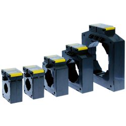 KCT-60, 600/5A KEPLER Current TransformerSpecial Price THB 400.00 Regular Price THB 500.00
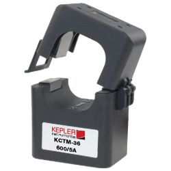 KCTM-36, 400/5A KEPLER Split Core Current TransformerSpecial Price THB 760.00 Regular Price THB 950.00
 KCTM-24, 100/5A KEPLER Split Core Current TransformerSpecial Price THB 680.00 Regular Price THB 850.00
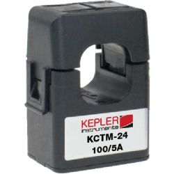 KCTM-24, 250/5A KEPLER Split Core Current TransformerSpecial Price THB 680.00 Regular Price THB 850.00
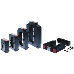 KCTS-23, 250/5A KEPLER Split Core Current TransformerSpecial Price THB 1,040.00 Regular Price THB 1,300.00
 KCTC-50, 1000/5A KEPLER Clamp-on Current TransformerSpecial Price THB 5,663.00 Regular Price THB 7,550.00
 KCTM-36, 600/5A KEPLER Split Core Current TransformerSpecial Price THB 800.00 Regular Price THB 1,000.00
Delivery: 4 ก.ย. 2569
What is a Current Transformer (CT)? How does it work? What should I consider when choosing one?
What is a current transformer, or CT for short? Why is it an essential component in control panels and high-voltage electrical systems? This article will delve into the details about what a current transformer is, from its basic function to its amazing working principles, all the way to how to select specifications that "match" your actual application for maximum safety and accuracy in your electrical system. If you need urgent consultation on selecting current transformers, contact our engineering teamhere
Get to Know the Current Transformer (CT) or Current Measuring Transformer
What is a current transformer, or CT? In electrical engineering, it is an instrument transformer that converts high currents in circuits (High Current) into lower standard values (Low Current), such as 1A or 5A, to safely connect with measuring devices (Meter), protection relays (Protection Relay), or other control equipment without directly connecting them to high-voltage lines. This not only enhances safety but also reduces the size and cost of these measuring instruments. Without a CT current transformer, measuring kiloampere currents would be extremely dangerous and cumbersome.
What is a CT? And why is it important in electrical systems?
CT acts as an "intermediary" between the power system (Power System) and the measurement control system (Instrumentation) by accurately transmitting current data in reduced form. The importance of CT is like the eyes of the electrical system; if CT provides incorrect values, measuring devices will display wrong readings, and protection relays may malfunction causing damage to expensive electrical equipment. Read more about ammeters here
Differences Between Current Transformer (CT) and Voltage Transformer (VT/PT)
While a current transformer is used to convert "current," voltage transformers (VT) or potential transformers (PT) are used to convert "voltage." Although both are types of transformers, their structures and circuit connections differ entirely. CT connects in series with the load (Series) to measure current flow, whereas VT connects in parallel with the circuit (Parallel) to measure voltage differences. Using them incorrectly can cause equipment explosions immediately.
Simplified Working Principle of Current Transformer
The basic principle of a current transformer operates on Faraday's law of electromagnetic induction, similar to that of a general power transformer. However, the design differs in that CT uses a large main conductor carrying current as the primary winding (Primary Winding), which usually consists of just one or a few turns (Bar Type). The secondary winding is wound around an iron core for multiple turns. When current flows through the main wire, it creates a magnetic field around the wire, inducing an electric current in the secondary winding at a ratio inversely proportional to the number of windings. For more detailed information on how it works, seehere.
Electromagnetic Induction in CT
When alternating current flows through a conductor, it generates magnetic flux lines that encircle the conductor. The iron core of the CT collects these magnetic flux lines and transfers them to the secondary winding, causing electron movement or electric current in the secondary circuit. This induced current is proportional to the primary circuit's current (Ratio), allowing us to calculate the actual current from measurements taken at the secondary windings.
Why does CT reduce electrical current?
According to the transformer formula $N_1 \times I_1 = N_2 \times I_2$ (number of turns x current), since the primary winding has very few turns (usually just one) and the secondary winding has many more, the resulting current on the secondary side is reduced proportionally. For example, a CT with a ratio of 100:5 means that if the input current is 100A, the output current will be reduced to only 5A (reduced by a factor of 20), making it safer for use.
Main Components of CT
The main components include 1. Core, made from silicon steel or high-permeability magnetic material; 2. Secondary winding (Secondary Winding), made from copper wire with insulation coating wound around the core; and 3. Insulation to prevent electrical leakage between windings and the core, or between the main conductor and the CT housing. The thickness of this insulation determines the voltage rating of the CT transformer.
How many types of Current Transformers are there? Which type should I choose?
The classification of current transformers can be done in several ways, both based on usage and physical structure. Choosing the wrong type may affect the accuracy and safety of the system.
Types Classified by Usage (Measuring vs. Protection CTs)
- Measuring CT (for measurement): Designed to have high accuracy in the normal load current range to ensure that ct meters read values correctly, but will saturate quickly when a short circuit occurs to prevent meter damage.
- Protection CT (for protection): Designed to operate even at currents much higher than the rating without saturating, to signal relays to trip circuits when abnormalities occur. Emphasizes reliability over precise accuracy.
Types Classified by Structure (Wound, Toroidal/Window, Bar-type)
- Wound Type: Has primary windings wound inside, suitable for low currents requiring high accuracy.
- Window/Toroidal Type: Donut-shaped with a central hole for wires to pass through. Most commonly used due to easy installation and cost-effectiveness.
- Bar-type: Has copper or aluminum bars as terminals, suitable for switchboard installations that must withstand mechanical forces from short circuits.
Comparison Table of Advantages and Disadvantages of Each Type of CT
(A comparison table should be included to help readers clearly understand, such as the Window Type being easy to install but accuracy may decrease if wiring is not done properly, while Wound Type offers high accuracy but is expensive and has limited current capacity.)
How to Select the Right Current Transformer for Your Work
Selecting a current transformer is not just about looking at the ampere rating; it involves considering several engineering factors to ensure accurate readings and prevent equipment damage.
Calculating the Correct CT Ratio
CT ratio refers to the ratio between primary and secondary current (e.g., 100/5, 400/5). The primary ampere rating should be slightly higher than the maximum load current (about 1.25 times) to ensure that the meter needle stays within a readable range with sufficient accuracy. However, selecting too high a ratio can lead to significant measurement errors in low current ranges.
Understanding Burden (VA)
Burden is the electrical load (Volt-Ampere) that the CT can supply while maintaining accuracy. The VA rating of the CT must be higher than the total VA of all connected devices (e.g., meters, cables). If the burden exceeds what the CT can handle, measured values will drop and become inaccurate.
Selecting the Accuracy Class
For electricity billing purposes, use Class 0.2 or 0.5 (with a 0.2% or 0.5% error rate). For general measurement in factories, Classes 1.0 or 3.0 are sufficient. Choosing an unnecessarily high class can make the current transformer overly expensive.
Window Size and Installation
The CT window size must be slightly larger than the wire or busbar to be inserted; if too tight, it may damage the insulation of the wires. If too loose and not centered properly, accuracy can be affected.
System Voltage
The CT insulation must withstand system voltage; for example, a Low Voltage (400V) system CT cannot be used in High Voltage systems due to insulation failure and potential ground faults. Learn more about equipment standards here.
Installation Steps and Safety Precautions
CT installation has strict safety rules that every electrician must memorize, as even minor errors can lead to life-threatening situations or equipment explosions.
Correct CT Installation (P1, P2 Direction)
On the transformer body, there are symbols for P1 (K) and P2 (L), indicating the direction of current flow. P1 must face the power source (Source) while P2 faces the load (Load). Reversing these can cause the watt-hour meter to spin in reverse or read incorrectly.
Danger of Secondary Open-Circuit
Never open the secondary circuit (S1, S2) of a CT while current is flowing through the primary side as it can induce extremely high voltage at the terminals, potentially causing insulation failure, sparks, or electric shock to workers. If removing meters, always short-circuit S1 and S2 together first.
Necessary Grounding
According to safety standards, one terminal of the secondary winding (usually S2) must be grounded to prevent danger if insulation between primary and secondary windings fails, allowing high voltage leakage into the measurement circuit.
Applications of Current Transformer in Industry
CT is widely used not only for measurement but also as a critical component of energy management and damage prevention systems.
Metering Electrical Energy with Power Meter
Low voltage CT meter is the most common form of use, where CT sends current signals to the Power Meter to calculate kW, kWh, kVar for billing and energy usage analysis. See more information here.
Use in Protective Relaying Systems
Works with Overcurrent Relay to cut off the circuit when current exceeds the limit, or works with Earth Fault Relay to prevent earth leakage. It helps protect motors and transformers from damage.
Use in Load Monitoring Systems
Uses CT signals fed into PLC or current transducer to monitor motor status, whether it is running normally, underloaded (Underload), or overloaded (Overload) for automatic production process control. Learn more about Transducers here.
If you are looking for Current Transformers, think of SCMA!
If you need high-quality, accurate and durable current transformers or special current transformer models that are hard to find, SCMA is ready to provide the solution. We offer a wide range of leading brands with an expert engineering team available for advice on selecting specifications, installation, and troubleshooting to ensure your electrical system operates at maximum efficiency and safety. View all products here.
Summary
Current Transformer is a small but crucial component in electrical systems. Understanding its working principles and proper selection methods can help engineers and electricians design and maintain systems professionally, reducing risks and saving costs over the long term. If you want to enhance safety and accuracy in electricity measurement, don't forget to consult SCMA experts. Contact us here.
Frequently Asked Questions
What does CT 100/5A mean?
It means this CT has a ratio of 100 to 5. If there is a current flow of 100 amps on the primary side, it will have a secondary output current of 5 amps, which is standard for most meters.
Do you always need to choose a CT with a higher current rating than the load?
Yes, it's advisable to select a primary current rating of CT slightly higher than the maximum load (e.g., for an 80A load use a 100/5A CT) to prevent CT saturation and damage. However, it shouldn't be too high as this can make low-current readings inaccurate.
What happens if you install CT in reverse polarity?
If P1/P2 terminals are reversed, the secondary current will have a phase shift of 180 degrees. This results in negative Watt (power) readings or significant discrepancies in total energy measurements for three-phase systems.
🤖 IFM Product Assistant
Ask about products, specs and replacement models
Hello 👋 I can answer your questions about IFM efector products.
Examples:
• What is the replacement model for PN2021?
• Which pressure sensor models cover 250 bar?
Examples:
• What is the replacement model for PN2021?
• Which pressure sensor models cover 250 bar?
🗑 Clear history