
SPECIAL PROMOTION — Up to 40% off across many product groups, until 31 December 2026 · Click to see all promotion itemsIFM, Sensor, Automation SystemMeasuring / Testing InstrumentsTemp Indicator, Control, T/C, RTD, TimerHeater, SCR Control, Solid State, Power Supply, Control CabinetField Measuring Instruments, Pressure Gauge, Level Control, Flow MeasurementEMC, Pneumatic, Solenoid ValveInspection Test Lamp, Head Light, Automotive Measuring InstrumentWeighing Scales, Marking Machine, PrintersEducational Training SystemsHot Line Tools & Equipment SPECIAL PROMOTION — Up to 40% off across many product groups, until 31 December 2026 · Click to see all promotion itemsIFM, Sensor, Automation SystemMeasuring / Testing InstrumentsTemp Indicator, Control, T/C, RTD, TimerHeater, SCR Control, Solid State, Power Supply, Control CabinetField Measuring Instruments, Pressure Gauge, Level Control, Flow MeasurementEMC, Pneumatic, Solenoid ValveInspection Test Lamp, Head Light, Automotive Measuring InstrumentWeighing Scales, Marking Machine, PrintersEducational Training SystemsHot Line Tools & Equipment View promotion items View all
Earth Testers
What are Earth Testers?
An Earth Tester is a device used to test the grounding system. It measures the resistance of the grounding system in an electrical installation to ensure effective protection against short circuits and leakage currents for safety purposes. The method involves sending an electric current from one electrode through the grounding system to another electrode, then measuring the voltage generated and calculating the ground system's resistance. A low value indicates a good connection, while a high value suggests a problem that needs immediate attention.
Types of Earth Testers
- Fall-of-Potential Earth Testers use the Fall-of-Potential method, which is commonly used to measure grounding system resistance.
- Clamp-On Earth Testers are used to measure grounding system resistance without interrupting power lines, making them convenient and quick to use.
- Soil Resistivity Testers are used to measure soil resistance for evaluating the quality of soil suitable for installing a grounding system.
Applications of Earth Testers
- Used to check the integrity of grounding systems in residential and commercial buildings, both completed or under construction, in the construction industry.
- Used to inspect grounding systems of machinery and electrical equipment for maintenance and upkeep in manufacturing industries.
- Used in the energy sector to prevent short circuits and leakage currents within factories.
Famous Brands of Earth Testers
- Chauvin Arnoux, a brand specializing in electrical testing tools with international recognition.
- Fluke, a leading brand known for quality and reliability.
- Hioki, a brand offering a wide range of products well-regarded in the electrical industry.
- KEPLER INSTRUMENTS, a brand providing various high-quality and reliable products.
- Kyoritsu, a Japanese brand renowned for durability and accuracy.
- Megger, a long-standing brand expert in manufacturing electrical testing equipment.
View Earth Testers Catalog: Click Here
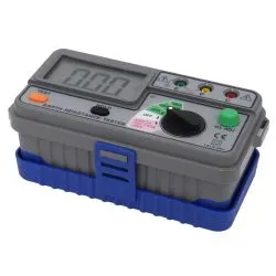 K1120 ER KEPLER 3 Wire Digital Earth TestersSpecial Price THB 7,600.00 Regular Price THB 9,500.00
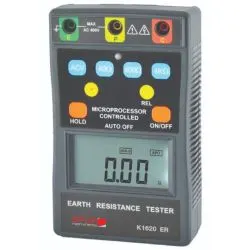 K1620 ER KEPLER 3 Wire Digital Earth TestersSpecial Price THB 7,680.00 Regular Price THB 9,600.00
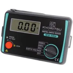 KEW 4105A KYORITSU 3 Wire Digital Earth TestersSpecial Price THB 7,200.00 Regular Price THB 9,000.00
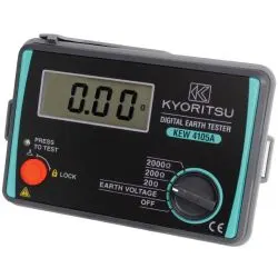 KEW 4105A-H KYORITSU 3 Wire Digital Earth TestersSpecial Price THB 10,350.00 Regular Price THB 13,800.00
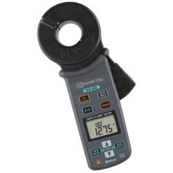 KEW 4200 KYORITSU Earth Clamp TestersSpecial Price THB 33,600.00 Regular Price THB 42,000.00
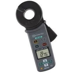 KEW 4202 KYORITSU Earth Clamp TestersSpecial Price THB 37,440.00 Regular Price THB 46,800.00
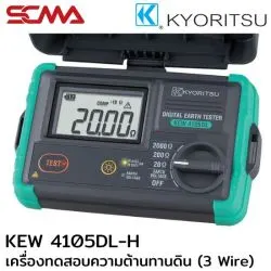 Kew 4105DL-H Kyoritsu 3-Wire Digital Earth TestersSpecial Price THB 15,440.00 Regular Price THB 19,300.00
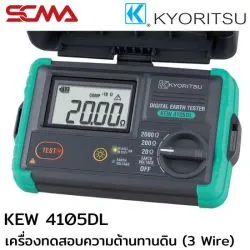 KEW 4105DL KYORITSU 3 Wire Digital Earth TestersSpecial Price THB 17,600.00 Regular Price THB 22,000.00
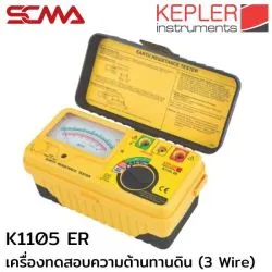 K1105 ER KEPLER 3 Wire Analog Earth TestersSpecial Price THB 7,600.00 Regular Price THB 9,500.00
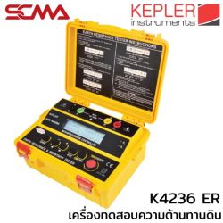 K4236 ER KEPLER 4 Wire Earth Resistance & Resistivity TestersSpecial Price THB 23,600.00 Regular Price THB 29,500.00
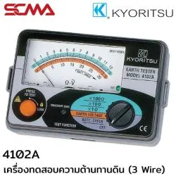 4102A KYORITSU 3 Wire Analog Earth TestersSpecial Price THB 5,760.00 Regular Price THB 7,200.00
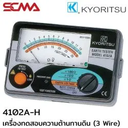 4102A-H KYORITSU 3 Wire Analog Earth TestersSpecial Price THB 10,240.00 Regular Price THB 12,800.00
Delivery: 30 ต.ค. 2569
 KEW 4106 KYORITSU 4 Wire Digital Earth TestersSpecial Price THB 50,250.00 Regular Price THB 67,000.00
Delivery: 30 ต.ค. 2569
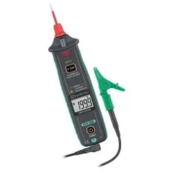 KEW 4300 KYORITSU Simplified Earth TestersSpecial Price THB 10,000.00 Regular Price THB 12,500.00
Delivery: 30 ต.ค. 2569
What is an Earth Tester? A Complete Guide to Usage and Selection
Safety in industrial electrical systems starts with a properly grounded system. If you are facing issues such as electric leakage, abnormal machine operation, or need to verify if your current earth tester is providing accurate readings, this article has the answers. This tool, commonly referred to by electricians as a ground resistance meter, is an essential device for checking the efficiency of grounding systems according to engineering standards. Choosing the right ground testing equipment and knowing how to read its measurements correctly can effectively prevent electrical shock accidents and damage to expensive electronic devices.
What is an Earth Tester (Ground Resistance Meter)?
An earth tester or ground resistance meter is a specialized electrical measuring instrument designed specifically for measuring the resistance between a grounding rod and the earth. The goal is to ensure that excess current from leakage or lightning can flow into the ground easily and quickly. A low earth resistance value (typically not exceeding 5 ohms according to standards) helps reduce dangerous touch voltages that may harm workers. This resistance value changes over time due to weather conditions and soil moisture levels, making regular checks an essential part of maintenance programs.
The Importance of the Earthing System
The earthing system acts as a safety path during emergencies. Without proper grounding or with excessively high resistance, leaking current may flow through other conductors instead, such as machinery frames or human bodies. Regularly using an earth tester to check the system ensures its readiness and reduces risks of production downtime due to electrical issues, extending the lifespan of equipment.
The Impact if Earth Resistance is Out of Standard
If measuring ground resistance reveals values above standard limits, severe damage can occur during lightning strikes or electric surges. Sensitive electronic devices like PLCs or controllers may be instantly damaged. Additionally, in case of leakage, residual current circuit breakers (ELCB) might not operate as intended, posing a risk to worker safety. Immediate corrective measures must be taken upon detecting any abnormalities.
The Working Principle of an Earth Tester
The basic principle of a ground tester in measuring earth resistance is based on Ohm's Law, where the device supplies current (I) into the ground through a grounding rod and measures the voltage drop (V) across it to calculate resistance (R = V/I). Various measurement methods exist depending on site conditions and chosen testing equipment. For more detailed information about working principles,click here.
Three-Pole (Fall of Potential) Measurement Method
The Fall of Potential or three-pole method is the standard and most accurate technique internationally recognized. The process involves driving two auxiliary earth spikes into the ground in a straight line away from the grounding rod to be measured. The tester sends alternating current through the farthest spike and measures voltage relative to the middle spike. This method suits new installations or large areas where additional stakes can be driven.
Clamp-On (Stakeless Testing) Measurement Method
The clamp-on ground meter is designed for convenience in maintenance without needing to drive auxiliary spikes or disconnect grounding wires. It uses a single clamp with an induction coil and current-measuring coil to induce constant voltage into the ground loop and measure returning current. Suitable for multi-grounded systems like utility poles or lightning protection on tall buildings.
Types of Earth Testers You Should Know
Ground testing technology continuously evolves to meet diverse field requirements. Choosing the right type of equipment ensures quick and reliable results.
Pole-Type (Analog Earth Tester)
The needle-type tester remains popular due to its affordability and no battery requirement for display (some models use hand cranking). Its advantage is easy observation of needle oscillation to gauge resistance stability, though users must be skilled in reading scales and adjusting multipliers.
Digital Earth Tester
Digital earth tester or digital ground meter replaces the needle type with clear numeric readings, reducing human error. New models often come with automatic calculation functions, memory for data logging, and earth voltage measurement capabilities to detect interference. Ideal for engineers requiring speed and accuracy.
Clamp-Type (Clamp-on Ground Tester)
The clamp-on ground resistance meter offers ultimate convenience for maintenance in urban or concrete areas where stakes cannot be driven. Simply clamp around the grounding wire to get immediate readings. However, this method has limitations as it requires a current loop; single rod measurements without connection to other systems yield inaccurate results. See type comparisonshere.
How to Choose the Right Earth Tester for Your Job Site
Choosing testing equipment isn't just about price but considering job characteristics for a cost-effective and practical solution.
Evaluate Based on Job Characteristics (New Installation vs. Maintenance)
For new installations in open areas, choose the three-pole method to measure true earth resistance accurately. For routine checks in factories with concrete floors, a clamp-on type saves time or opt for hybrid models offering both methods.
Accuracy and Measurement Range
Check if the tester's specifications cover your required measurement range. General work may require 0-2000 ohms, while some jobs need decimal precision in lower ranges. Accuracy should meet standards like ISO.
Consider Bluetooth Connectivity and Memory for Data Logging
For clients requiring data logs, models with Bluetooth connectivity or memory logging reduce documentation steps and errors. IP ratings are crucial for field equipment exposed to dust and mud.
Recommended Earth Tester Models (Kyoritsu, Fluke, etc.)
When it comes to Kyoritsu earth testers, Thai electricians have long trusted their durability and accuracy.
- Kyoritsu 4105A: A legendary model that sets the standard for Kyoritsu, offering easy digital use, durability, and good dust/water resistance. Suitable for general field work.
- Kyoritsu 4200/4202: For those seeking a cost-effective clamp-on model, this one meets expectations with accurate technology and easy use in tight spaces.
- Kyoritsu 4102A: An analog (needle) model for those preferring classic design at the lowest price, still providing reliable measurements.
If you're looking for Kyoritsu earth testers or other models like new releases, check specifications and compare technologies from international sourceshere.
Think of SCMA When You Need an Earth Tester!
Electrical system safety is non-negotiable. Having a Kyoritsu or other leading brand tester ensures valuable investment in safety. SCMA offers expert advice on selecting the right ground resistance meter for your needs, whether new installations or maintenance. Our team of engineers provides demonstrations and quick after-sales service, ensuring genuine quality products 100%. Browse all productshere.
Summary
An earth tester is a crucial tool for verifying electrical system safety. Properly selecting and regularly checking equipment, whether three-pole or clamp-on types, protects lives and assets in factories. SCMA hopes this article helps you understand and professionally choose the right ground meter. For further consultation,contact us here.
Frequently Asked Questions
What should standard earth resistance be?
According to Thai electrical installation standards, system grounding resistance should not exceed 5 ohms for easy current flow and timely circuit breaker operation. However, in areas with high soil resistance, allowances or soil improvement methods may apply.
Can clamp-on testers be used on single rods?
No, clamp-on testing relies on current loops; single rods not connected to other systems won't form complete circuits, leading to inaccurate readings or excessively high values. Use three-pole methods for single rods.
How often should earth testers be calibrated?
Calibration is recommended annually according to ISO standards, especially for frequently used Kyoritsu models or those subjected to impacts. Immediate checks are advised after heavy use or impacts.
This website uses cookies
We use cookies to make the site work properly, to understand how it is used, and to show content that is relevant to you. You choose which types to allow; strictly necessary cookies are always on. Privacy Policy
🤖 AI Assistant
Ask about products, specs and replacement models
Hello 👋 Ask us anything — find products, compare specs, or troubleshoot.
🗑 Clear history