
SPECIAL PROMOTION — Up to 40% off across many product groups, until 31 December 2026 · Click to see all promotion itemsIFM, Sensor, Automation SystemMeasuring / Testing InstrumentsTemp Indicator, Control, T/C, RTD, TimerHeater, SCR Control, Solid State, Power Supply, Control CabinetField Measuring Instruments, Pressure Gauge, Level Control, Flow MeasurementEMC, Pneumatic, Solenoid ValveInspection Test Lamp, Head Light, Automotive Measuring InstrumentWeighing Scales, Marking Machine, PrintersEducational Training SystemsHot Line Tools & Equipment SPECIAL PROMOTION — Up to 40% off across many product groups, until 31 December 2026 · Click to see all promotion itemsIFM, Sensor, Automation SystemMeasuring / Testing InstrumentsTemp Indicator, Control, T/C, RTD, TimerHeater, SCR Control, Solid State, Power Supply, Control CabinetField Measuring Instruments, Pressure Gauge, Level Control, Flow MeasurementEMC, Pneumatic, Solenoid ValveInspection Test Lamp, Head Light, Automotive Measuring InstrumentWeighing Scales, Marking Machine, PrintersEducational Training SystemsHot Line Tools & Equipment View promotion items View all
Current Transducers
What are Current Transducers?
Current Transducers are devices used to convert electrical current signals into other types of electrical signals for measurement, monitoring, or control in automatic systems. The converted signal is often voltage (Voltage) or digital signals that can be used with automatic control systems (PLC) and energy management systems (EMS). This conversion uses various technologies such as:
- Hall Effect, which occurs when an electric current flows through a conductor in a magnetic field, generating voltage perpendicular to the current and the magnetic field.
- Rogowski Coil, using an air-core coil as a detector. When current flows, it induces voltage according to electromagnetic induction principles.
- Shunt Resistor, using a low-value resistor to measure the voltage drop caused by the current flow and then converting that voltage into the desired electrical signal.
Types of Current Transducers
- Analog Current Transducers convert electric current signals into usable voltage or other types of current signals.
- Digital Current Transducers convert electric current signals into digital signals that can be used with automatic control systems and energy management systems.
- AC Current Transducers are used to convert AC (alternating current) signals into other types of electrical signals.
- DC Current Transducers are used to convert DC (direct current) signals into other types of electrical signals.
Applications of Current Transducers
- Used for measuring and monitoring electric currents in various power systems, maintenance, and energy management. They are also used to check and measure current in electricity stations and power distribution systems in the energy industry.
- Connected with automatic control systems (PLC) and energy management systems (EMS) for controlling and monitoring system operations, including managing electric currents in manufacturing machinery and electrical equipment.
- Used to protect power systems by checking and analyzing current within the system. They are also used during installation and inspection of building and construction industry projects.
- Used for inspecting and analyzing electrical systems in electric vehicles in the automotive industry.
Famous Brands of Current Transducers
- ABB, a brand with diverse products specializing in energy management.
- CR Magnetics, a brand specialized in producing current transducers and electrical measuring devices.
- Honeywell, a high-quality product brand specializing in energy management and automatic control systems.
- LEM, a leading brand renowned for producing high-quality current transducers.
- Seneca, products with unique characteristics that are easily recognizable and distinct from other brands in the market.
- Siemens, a brand expert in technology and innovation for electrical systems.
View Current Transducers Catalog : Click here
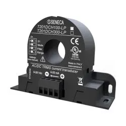 T201DCH100-LP AC/DC CURRENT TRANSDUCERS SENECASpecial Price THB 4,500.00 Regular Price THB 6,000.00
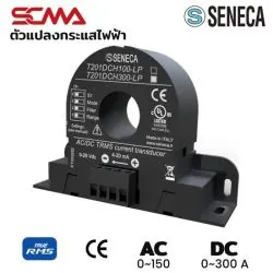 T201DCH300-LP SENECAC/DC Current TransducersSpecial Price THB 5,200.00 Regular Price THB 6,500.00
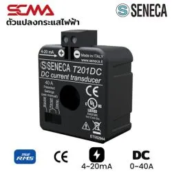 T201DC SENECa Current Transduc ersSpecial Price THB 5,200.00 Regular Price THB 6,500.00
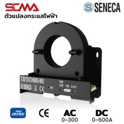 T201DCH600-MU SENECA AC/DC Current TransducersSpecial Price THB 7,680.00 Regular Price THB 9,600.00
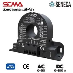 T201DCH100-M SENECAC/DC Current TransducersSpecial Price THB 5,440.00 Regular Price THB 6,800.00
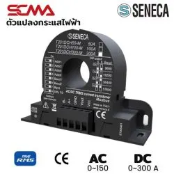 T201DCH300-M SENECAC/DC Current TransducersSpecial Price THB 5,840.00 Regular Price THB 7,300.00
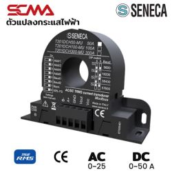 T201DCH50-MU SENECA AC/DC Current TransducersSpecial Price THB 4,960.00 Regular Price THB 6,200.00
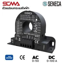 T201DCH100-MU SENECA AC/DC Current TransducersSpecial Price THB 6,400.00 Regular Price THB 8,000.00
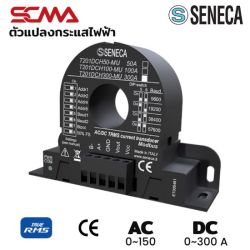 T201DCH300-MU SENECA AC/DC Current TransducersSpecial Price THB 6,880.00 Regular Price THB 8,600.00
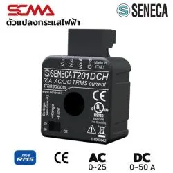 T201DCH SENECAC/DC Current TransducersSpecial Price THB 3,200.00 Regular Price THB 4,000.00
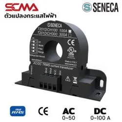 T201DCH100 SENECAC/DC Current TransducersSpecial Price THB 5,200.00 Regular Price THB 6,500.00
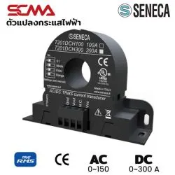 T201DCH300 SENECAC/DC Current TransducersSpecial Price THB 5,440.00 Regular Price THB 6,800.00
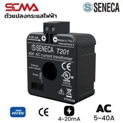 T201 Seneca Current TransducersSpecial Price THB 3,200.00 Regular Price THB 4,000.00
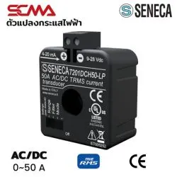 T201DCH50-LP SENECAC/DC Current TransducersSpecial Price THB 3,280.00 Regular Price THB 4,100.00
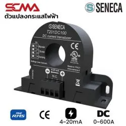 T201DC100 SENECAN Current TransducersSpecial Price THB 6,880.00 Regular Price THB 8,600.00
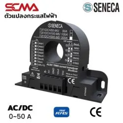 T201DCH50-M SENECAC/DC Current TransducersSpecial Price THB 4,480.00 Regular Price THB 5,600.00
What is a Current Transducer? A Complete Guide to Types and Principles
Why are current transducers or transducers important in industrial electrical systems? This small device converts electrical current signals into easily understandable data for control systems, which is crucial for monitoring and preventing damage in factories. If you're looking for answers on how this type of current converter works, what types there are, and how they differ from general current sensors, this article will delve into all the details to help you choose the right one effectively and cost-effectively. For immediate consultation with an expert, contact ushere.
What is a Current Transducer?
A current transducer is an electronic device that detects the primary electrical current in the main circuit (Primary Current), whether it's alternating current (AC) or direct current (DC), and converts the measured value into a standard electrical signal in another form (Secondary Signal) proportionally, such as analog signals like 4-20mA, 0-5V, or digital signals to be accurately transmitted to control devices like PLCs, controllers, or data loggers. This device is crucial in Industry 4.0 where real-time data is needed for analysis and decision-making by serving as a communication intermediary between power circuits and electronic control systems.
The Main Function of Current Transducers in Electrical and Electronic Systems
The main function of current transducers is to "convert" and "isolate" signals. Electric isolation between high-voltage power circuits and low-voltage control circuits is crucial for the safety of both equipment and users. Additionally, they condition signals to be stable, reduce noise, and transmit them over long distances without losing accuracy, which is necessary for SCADA or BMS systems in large buildings.
Why Do We Use Transducers Instead of Direct Current Measurement?
Direct measurement (Direct Measurement) by connecting an ammeter in series with the circuit has several limitations, especially when measuring high currents that are dangerous and require large equipment. Transducers solve this problem by using magnetic field or induction methods for non-intrusive measurements, making installation easier, safer, and without voltage drop in the system. They also measure rapidly changing or high-frequency currents better than basic measurement tools. Learn morehere.
Basic Working Principles of Current Transducers
The working principle of current transducers is based on electromagnetic theory, detecting the magnetic field around a conductor carrying current according to Ampere's law. Popular technologies include Hall Effect for DC/AC and Current Transformer for AC measurement, each with unique advantages. Understanding these principles helps engineers select devices that best match their applications.
Hall Effect Principle
Hall Effect technology is widely used in current transducers to measure both DC and AC currents. The principle involves a voltage drop across the edges of a conductor plate when a magnetic field interacts with it, proportional to the magnetic field strength (and the current flowing through the wire). Internal electronics amplify this signal into standard output signals. Advantages include fast response and versatile waveform measurement.
Current Transformer Principle
For AC current measurements, magnetic induction technology using a current transformer (CT) remains the most economical and robust method. The primary coil's current induces secondary coil currents according to wire turns ratio, which are then converted into DC output signals as required. Learn more about Transmittershere.
Rogowski Coil Principle
This technology uses an air-core coil wound around a conductor to measure AC currents. Its advantage is no iron core, avoiding magnetic saturation issues and allowing high current or sudden change measurements with ease. It's lightweight, flexible, and easy to install in tight spaces, often used for electrical power quality analysis.
Popular Types of Current Transducers
Current transducer types are categorized based on internal circuitry and installation methods, directly affecting accuracy and cost. Choosing the right type saves budget and maximizes efficiency.
Open Loop (Open Circuit): Advantages and Limitations
The Open Loop uses Hall Effect sensors to measure magnetic fields directly, amplifying signals. Advantages include simple structure, small size, lightweight, cost-effective, and low power consumption, suitable for general applications requiring moderate accuracy. Limitations include temperature-related errors and non-linear magnetic field issues.
Closed Loop (Closed Circuit): For Maximum Accuracy
Also known as Zero Flux, this type feeds back current into the secondary coil to create opposing magnetic fields until the core's magnetic field is zero. The feedback current accurately mirrors primary currents, providing high accuracy, fast response, and excellent linearity, ideal for high-precision applications like motor control in robots.
Split-Core (Separable Core): For Easy Installation
The Split-Core design allows the iron core to open and close, enabling installation around existing wires without disconnecting them or shutting down power systems. Ideal for retrofit projects or temporary energy audits, significantly reducing installation time and costs.
Clear Comparison: Current Transducer vs. Current Sensor vs. Current Transformer
Confusion between these three is common despite similar current measurement functions. Technically, CT reduces AC currents proportionally (e.g., 100/5A) and connects to ammeters, while sensors provide low voltage signals or require external circuits. Transducers are complete units with signal conditioning circuits providing standard outputs like 4-20mA for automation systems immediately. Learn more about current measurement basicshere.
Differences in Working Principles and Output Signals
Key differences include output signals: CT provides AC current, sensors provide low voltage, transducers offer standard (DC) signals that can travel long distances with noise resistance. Transducers typically require auxiliary power while CTs do not.
Summary Table: What to Choose When?
|
Device |
Suitable For |
Output Signal |
Powersupply |
|
Current Transformer |
General AC current measurement, connects to panel meters |
AC Current (Ratio) |
No power required |
|
Current Sensor |
PCB, electronic circuits |
Low voltage signals |
No power required |
|
Current Transducer |
Automation systems, energy management |
Standard signals like 4-20mA or 0-10V |
Auxiliary power required |
Considerations for Choosing a Current Transducer
Choosing the right current transducer involves considering current range, AC/DC types, accuracy and linearity, output signal formats, installation environment, and physical size.
Current Range and Type (AC/DC)
Identify the highest current to be measured (Peak Current) and select an appropriate measurement range. Avoid overestimating ranges as it reduces resolution.
Accuracy and Linearity
High-precision applications like energy trading calculations require accuracy classes of 0.5 or 0.2, while general monitoring class 1.0 is sufficient. Good linearity ensures accurate readings across the measurement range.
Output Signal Formats (e.g., 4-20mA, 0-5V, 0-10V)
Select formats compatible with receiving equipment inputs. 4-20mA signals are popular in industries due to noise resistance and fault detection capabilities, while 0-10V is common for building automation.
Installation Environment and Physical Size
Consider installation space, wire slot size, operating temperature, and dust/water protection ratings. Compact models are advantageous in crowded control cabinets.
Current Transducer Applications in Industries
Current transducers play a role in almost every industry using electricity, enhancing efficiency and energy savings.
Motor Monitoring and Drive Systems
Used to measure motor currents for load analysis, detecting abnormalities like overloads, phase loss, or bearing failures reflected in abnormal current patterns. Helps with predictive maintenance.
Renewable Energy Systems (Solar Inverters, Wind Turbines)
In solar systems, measuring DC currents from panels and AC currents from inverters is necessary for calculating production efficiency and controlling system operation relative to the grid.
Building and Factory Energy Management
Used in EMS systems to track individual machine or department energy usage, identify wasteful consumption points, and plan targeted energy savings. View meter data here.
If You're Looking for a Current Transducer, Think SCMA!
(Note: This section may have been mistakenly printed as Turbine Flow Meter instead of Current Transducer. For information on Current Transducers, it would be as follows)
If your factory is looking for high-quality, accurate, and durable current transducers, SCMA has the solution with a variety of models supporting all current ranges and output signal formats. Our team of experts provides advice on selecting specifications and installation to offer you cost-effective solutions tailored to your needs. View all products here.
Summary
Current transducers are like the eyes of electrical control systems. Choosing high-quality devices suitable for your application will help you clearly see electricity usage patterns, leading to precise control, energy savings, and maximum safety in power systems. If you want to enhance your electrical monitoring system, don't hesitate to consult SCMA experts here.
Frequently Asked Questions
Does a Current Transducer Require Power Supply?
Most transducers require auxiliary power supplies like 24VDC or 220VAC to power internal electronics. Some models are loop-powered (using signal loop power) or self-powered (using measured current), but these have different usage limitations.
Is Installing a Current Transducer Difficult?
Not difficult, especially with split-core models designed for easy installation by simply clamping wires. However, be cautious about current direction (check the device's arrow) and correct signal wiring to ensure accurate readings.
Can a Single Transducer Measure Both AC and DC Currents?
Yes, if you choose models with Hall Effect sensors that respond to both constant (DC) and changing (AC) magnetic fields. These models are typically specified as AC/DC or True RMS, offering great convenience and value for versatile applications. Learn morehere.
This website uses cookies
We use cookies to make the site work properly, to understand how it is used, and to show content that is relevant to you. You choose which types to allow; strictly necessary cookies are always on. Privacy Policy
🤖 AI Assistant
Ask about products, specs and replacement models
Hello 👋 Ask us anything — find products, compare specs, or troubleshoot.
🗑 Clear history