
Directional Valve
What is a Directional Valve: A Complete Guide to Control Valves
Have you ever wondered how automated machinery knows when to extend an actuator or which direction a hydraulic motor should turn? Behind these precise movements lies a crucial component called the Directional Valve, also known as a control valve. This article delves into every aspect of this device, from its basic operating principles and various types that engineers need to know about, to easy-to-understand methods for reading valve symbols, all the way to tips on selecting the right one for optimal system performance.
Main Functions of E.MC Directional Valve
- Controls the direction of compressed air flow. It is a critical component in pneumatic systems that determines the path of compressed air movement within the system, such as directing it into an actuator to move forward or backward.
- Controls the opening and closing of air flow. Can be used to stop or allow air to pass through.
Distinguishing Features of E.MC Directional Valve
- High quality and durable: Made from standard materials.
- High efficiency: Enables pneumatic systems to operate quickly and accurately.
- Variety: Offers a range of models and sizes suitable for different system requirements and control types.
- Competitive pricing: EMC is known for providing efficient pneumatic solutions at cost-effective prices.
View the E.MC PNEUMATIC Catalog Click Here
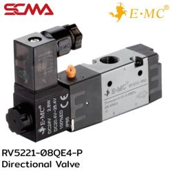 RV5221-08QE4-P \ Solenoid Valve \ 5/2 Single Control DC24V / PT1/4” \ E.MCSpecial Price THB 345.00 Regular Price THB 460.00
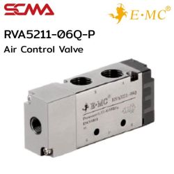 RVA5211-06Q-P \ 5/2 Single control / PT1/8” \ E.MCSpecial Price THB 300.00 Regular Price THB 400.00
What is a Directional Valve? A Complete Guide to Directional Control Valves
Have you ever wondered how an automatic machine knows when to extend the cylinder or which direction a hydraulic motor should turn? Behind these precise movements lies a crucial component called a Directional Valve, also known as a directional control valve. This article will delve into every aspect of this device, from its basic working principles, various types that engineers need to know about, easy-to-understand valve symbol reading methods, all the way to tips on selecting the right one for optimal automation system performance. If you require immediate consultation regarding valves and system design, contact our engineering team here.
What is a Directional Valve? Understanding its Primary Function
A Directional Valve or in full name Directional Control Valve (DCV) is an essential component in fluid power systems, functioning like traffic control that directs the flow of compressed air in pneumatic systems or oil in hydraulic systems along predetermined paths to command actuators such as cylinders or motors to stop, move forward, or reverse. The primary function of this type of valve can be summarized into three aspects: stopping the flow (Stop), allowing the flow (Allow Flow), and changing the direction of the flow (Change Direction).
Important Role in Pneumatic and Hydraulic Systems
In automation, air valves and oil valves are considered the command centers that receive signals from controllers or sensors and translate them into mechanical commands. If compared to a human body, an air pump or hydraulic pump is like the heart pumping blood, pipelines are like veins, and pneumatic directional control valves are the nervous system instructing muscles (cylinders) to move as required. Without this component, the system cannot control timing or direction of operation at all, making machines nothing more than erratic metal pieces.
Differences Between Directional Control Valves, Flow Rate, and Pressure
Many people often confuse between different types of valves. It's important to understand that a Directional Control Valve focuses on controlling the "direction" of flow, whereas a Flow Control Valve controls the "quantity" of flow for speed adjustment and a Pressure Control Valve controls "pressure" to limit system force. Although some models of directional control valves may throttle flow somewhat (Proportional Valves), their primary function remains setting the path rather than directly adjusting speed or pressure.
Basic Operation Principle of Directional Control Valve
The mechanism of a Directional Valve, especially the sliding type (Sliding Spool), relies on the movement of an internal shaft called "Spool" that slides within the valve housing to open or close fluid pathways. When the Spool moves to one position, grooves on the shaft align with ports allowing fluid flow through, but when it shifts to another position, the metal body of the Spool blocks those ports, stopping flow or redirecting it to other ports instead. This principle applies both to pneumatic and hydraulic valves.
Main Components: Body and Valve Spool
The valve body serves as the external structure with ports connecting to external pipes, and it has a cylindrical cavity inside for the Spool to move within. The Spool is a metal shaft with alternating raised (Land) and recessed (Groove) sections. Precision in manufacturing the Spool and body is crucial to minimize internal leakage without using contacting rubber seals, which reduces friction and extends service life.
Spool Movement for Changing Flow Direction
Actuating the Spool movement can be done in several ways called "Actuation Method," such as manually pressing a lever, using an electromagnet in a solenoid valve, or utilizing compressed air (Air Pilot). When force is applied to the Spool, it shifts positions (Switching Position), changing the flow direction. Once the actuating force ceases, internal springs typically return the Spool to its normal position.
Types of Directional Valves You Should Know About
The classification of directional control valves is commonly referred to by the "number of ports (holes)" and "number of positions (rooms)", which is an international standard. Understanding these numeric codes will help in selecting the correct valve according to the desired function, where the first digit indicates the number of inlet-outlet holes and the second digit indicates the possible operating states.
Categorized by Number of Ports and Positions: 2/2, 3/2, 4/2, 5/2, 5/3
- Valve 2/2: Has 2 holes and 2 positions, functioning as an on-off flow control similar to a water tap.
- Valve 3/2: Has 3 holes and 2 positions, commonly used to control single-acting pneumatic cylinders. The third hole is for air exhaust.
- Valve 5/2: or Valve 5/2 Has 5 holes and 2 positions, a star in pneumatics used to control double-acting pneumatic cylinders for extension-retraction.
- Valve 5/3: Adds a center position to stop the cylinder in mid-stroke or allow it to float (Float).
Categorized by Actuation Method: Hand-operated Valve, Electric Valve (Solenoid Valve), Pneumatically Operated Valve
Solenoid valves are the most popular type in automatic systems because they can be directly controlled by electricity from a PLC. Manual hand or foot-operated valves are used where human control is required, and pneumatically operated valves are used in explosive-proof areas without electricity or when high actuating force is needed. The choice of actuation method should consider job suitability and safety primarily. Learn more about solenoid valveshere.
The Difference Between Mono-stable and Bi-stable
Mono-stable valves (Single Solenoid) have a return spring, so when power is cut off, the valve immediately returns to its original position. Suitable for safety-critical applications (Fail-safe). Bi-stable valves (Double Solenoid) do not have a return spring; the valve retains its last state even after power loss and requires power on another side to change positions. Suitable for jobs that require maintaining status during power failure.
How to Read the Basic Symbol of a Directional Control Valve
Reading valve symbols according to ISO 1219 standards is a fundamental skill that engineers must have. These symbols indicate all functions without having to see the actual device, making circuit design and maintenance easier and faster.
Meaning of Rectangles (Positions)
In pneumatic or hydraulic valve symbols, each rectangle represents "1 working position." If a valve has 2 rectangles, it is a 2-position valve (2-Position). If there are 3 rectangles, it is a 3-position valve (3-Position). Typically, we look at the tube connections in the "normal position" (Normal Position), which usually lies on the right or center.
Meaning of Arrows and Lines (Flow Direction)
Inside each rectangle, there are lines and arrows
- Arrows: Indicate the direction of fluid flow.
- Solid Line (T): Indicates that the port is blocked, preventing flow.
- Port Holes: Points where lines touch the rectangle's edge (count only within one box) indicate the number of ports. For example, Valve Symbol 5 2 has 5 contact points.
Symbols for Various Actuation Types
On the sides of the rectangle, there are symbols indicating actuation methods such as:
- Diagonal line in a small box: Solenoid (Solenoid)
- Ribbed Line: Spring Return (Spring Return)
- Toggle Switch: Lever (Lever)
- Push Button: Push Button
These symbols help us know how to actuate the valve and what returns it to its original state. See more about directional control valve symbols at https://en.wikipedia.org/wiki/Control_valve
Applications in Various Industries
Directional control valves are integrated into every industry, from agricultural machinery to advanced robot assembly lines. Selecting the correct type of valve is crucial for system efficiency.
Pneumatic System Example Applications
In manufacturing plants, a 5/2 valve is used to control air cylinders in pick and place operations, push boxes onto conveyor belts, or open and close machine doors. These valves must operate at high speed (High Cycle) and withstand millions of repetitive cycles. Read more about pneumatic systemshere.
Hydraulic System Example Applications
A Macroc excavator uses manual lever directional control valves to smoothly operate the boom, arm, and bucket while handling massive pressure. In metal stamping machines (Press Machine), large solenoid hydraulic valves are used to precisely control die pressing force.
Guide for Selecting Directional Valves Appropriately
Incorrect valve selection can lead to system inefficiency, overheating, or damage. Factors to consider go beyond thread size and include engineering properties.
Factors to Consider: Flow Rate, Operating Pressure
The valve size must accommodate the flow rate required by end equipment; if too small, pressure drop will occur, slowing cylinder movement. Also, check that the maximum operating pressure (Max Pressure) is within the valve's capacity, especially in high-pressure hydraulic systems.
Fluid Type Selection: Air, Hydraulic Oil
Valve seals must be compatible with the fluid type; pneumatic valves often use NBR seals and aluminum housings, while hydraulic valves use cast iron bodies and oil-resistant seals. Using incorrect types can cause seal swelling or corrosion leading to leaks and sticking.
Environmental Conditions and Installation Temperature
In explosive environments, explosion-proof solenoid valves must be used; for outdoor installations in wet areas, IP65 or higher models should be chosen with coils that can withstand environmental temperatures without burning.
If You Are Looking for Directional Valves, Think SCMA!
If your factory is seeking high-quality directional valves or replacement parts for damaged control valves but unsure about specifications or replacements, SCMA is ready to provide engineering consultation. Our team of experts can assist with model comparisons, installation recommendations, and sourcing valves from leading brands worldwide to get your machinery back up and running quickly and efficiently at peak performance. View all valve productshere.
Summary
A Directional Valve is the core component for controlling movement in an automated system. Having a proper understanding of its working principles, types, and symbol reading will enable engineers and maintenance technicians to select and maintain equipment efficiently, extend machine life, and reduce production downtime. If you wish to enhance your directional control systems with precision and durability, SCMA offers international standards services. Contact us for free consultation here.
Frequently Asked Questions
Is a Solenoid Valve a Directional Valve?
Yes, a Solenoid Valve is one type of Directional Valve that uses electromagnetic actuation to shift the valve position. It is the most common in automated systems, but there are other types such as manual or air-operated Directional Valves.
What is the difference between Normally Open (NO) and Normally Closed (NC) valves?
Normally Closed (NC), or normally closed, means that in normal conditions (without power supply), the valve will be shut to prevent flow. When powered, it opens. Conversely, Normally Open (NO), or normally open, means that under normal conditions, the valve remains open for continuous flow until power is applied to close it. The choice depends on safety requirements when power fails.
How do you perform basic maintenance on directional control valves?
The most important aspect is the cleanliness of the fluid in pneumatic systems, where an air filter regulator (FRL) set must be installed to trap water and dust. For more information, see here. In hydraulic systems, oil filters need regular replacement; contaminants getting into the Spool are the main cause of valve sticking or leakage.
🤖 IFM Product Assistant
Ask about products, specs and replacement models
Hello 👋 I can answer your questions about IFM efector products.
Examples:
• What is the replacement model for PN2021?
• Which pressure sensor models cover 250 bar?
Examples:
• What is the replacement model for PN2021?
• Which pressure sensor models cover 250 bar?
🗑 Clear history