Is your factory facing issues with inaccurate electrical measurements or concerns about the safety of your main machinery? Choosing a Current Transformer (CT) that meets standards is crucial to solving these problems. The expert engineering team from SCMA is ready to provide accurate measurement system design solutions. This article will take you deep into the working principles, a checklist for purchasing, so that you can perfectly enhance the stability of your production process.
What is a Current Transformer (CT)?
Current Transformer (CT) provides a secondary signal proportional to the primary alternating current, allowing meters or relays to function. Specifications to consider include the ratio, insulation rating, and usage for measurement or protection. Read more about What is a current transformer

Working Principle of Current Transformer (CT)
The alternating current on the primary side creates a magnetic flux in the core and induces a signal on the secondary side. The error depends on the ratio, load, and operating range of the model. Learn more about Current Transformer here

How many types of Current Transformers (CT) are there?
Selecting the type of Current Transformer (CT) that matches the actual on-site conditions is essential to ensure the most accurate measurement results. The structure of Current Transformers in the industrial market can be divided into 4 types as follows
Primary Wound Type (Wound Primary CT)
This type of structure has a primary winding wound around the magnetic core with a specific number of turns. This type of device is designed for current measurement at points with low current values. The technical team recommends using it in circuits that require high precision in display results
Busbar Type (Bar-Type CT)
This type of device uses a copper or aluminum busbar inside the control cabinet as a substitute for the primary winding. The structure is strong and durable against high current levels. This type is suitable for installation in the main power supply systems of large factories
Through Type (Window-Type CT)
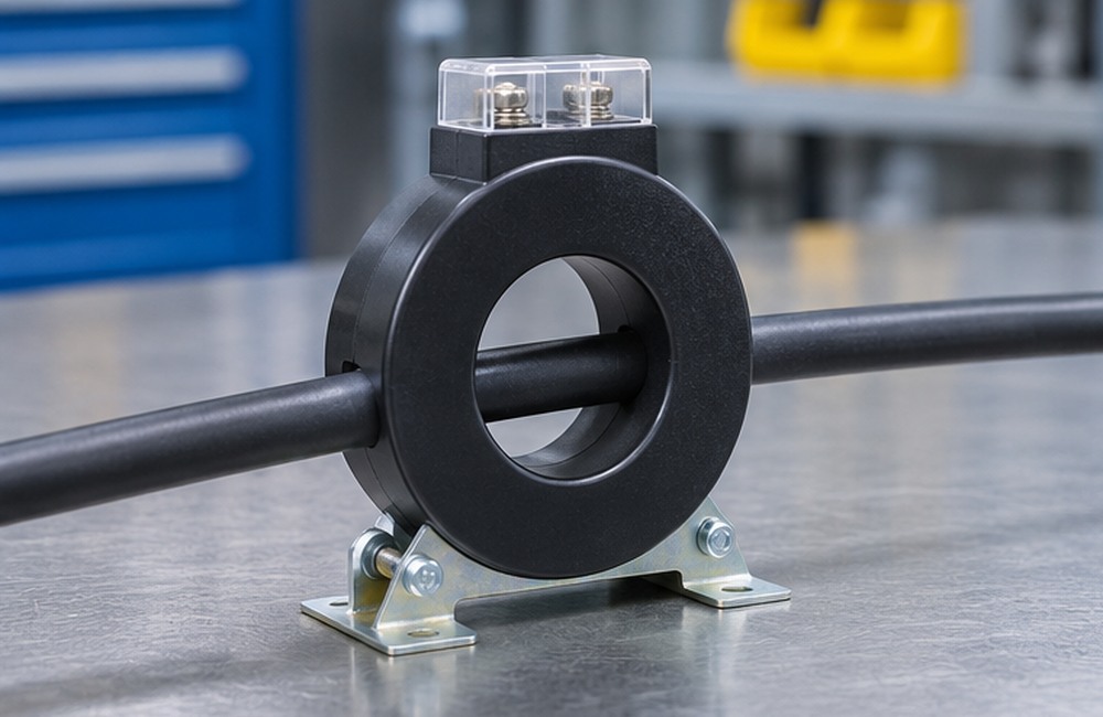
The device has a central gap designed to allow the main power cable or busbar to pass through quickly. The through-type usage helps save time in assembling the MDB cabinet. Most electrical engineers prefer this type due to the convenience in wiring View detailed information about Current Transformers
Split-Core Type (Split-Core CT)
Split-core CT opens the core to allow it to be placed around the original conductor without cutting the conductor. Therefore, it is suitable for system improvement work, allowing the power source to be disconnected and isolated, and confirming the voltage-free condition before installation according to electrical work procedures
Maintenance of Current Transformer CT
Proper maintenance of Current Transformer CT helps extend its lifespan and prevent serious damage to the factory electrical system. The basic standard engineering maintenance procedures consist of 4 important steps as follows
Visual Inspection
Operators should regularly inspect for cracks, dents, or rust on the external casing. Degraded insulation may cause electric leakage hazards. If any physical abnormalities are found, consider replacing the device with a new one.
Checking Terminal Tightness
Qualified personnel should inspect and tighten the terminals according to the manufacturer's torque values. After disconnecting and isolating the power source, confirm that there is no voltage and follow the on-site procedures.
Proper Cleaning
Clean after disconnecting the power and confirming that it is safe. Use tools and cleaning methods as specified in the equipment and switchgear manual.
Moisture Prevention in the System
Moisture is a critical factor that reduces the insulation performance of electrical equipment. Install the device in a dry area with an appropriate ventilation system. If it is necessary to use it in a risky environment, consider using additional moisture-resistant materials Learn more about What is CT
Application of Current Transformer CT in Industry
The manufacturing sector uses Current Transformer CT to maintain a stable working environment for machinery. The application of Current Transformers is divided into 3 main aspects to support business continuity.
Energy Measurement and Display (Metering)
The device is connected to a Power Meter to monitor current values and power within the system. The data obtained is highly accurate, helping managers analyze energy costs to find ways to reduce factory expenses.
Electrical Protection System (Relay Protection)
Protection CT sends current signals to the protection relay. The relay evaluates conditions based on set values and may command the device to trip the circuit. Appropriate performance depends on system design and joint testing.
Monitoring Production Process Efficiency
Maintenance engineers use Current Transformers to analyze motor load operation. Continuous energy usage data recording helps identify areas of waste, leading to effective proactive improvements in the production process.
Advantages of Current Transformers CT
Installing a high-quality Current Transformer CT is a long-term valuable investment for operators. In addition to current conversion, Current Transformers also provide 5 important engineering benefits
Isolating the measuring circuit from the power system
CTs with appropriate insulation and ratings help isolate the secondary circuit from the measuring circuit. However, the secondary terminals of current output CTs may generate dangerous voltages if the circuit is opened while primary current is present
Supporting massive electric currents
Some current output CT models provide secondary ratings of 1 A or 5 A, while voltage signal models have different conditions. Choose an output that is compatible with the signal receiving device
Improving data management accuracy
Calculating production costs requires a reliable numerical database. High-quality devices reduce the percentage of signal conversion error, resulting in accurate energy cost calculations and preventing profit loss
Protecting the power network system
For protection applications, select the class and performance in the fault current range that is suitable for relays and systems, so that relays receive signals according to the designed conditions
Easy installation and integration
Ring type and split core types meet different conductor types and installation space requirements. Installation and inspection work should be carried out by qualified personnel following the energy source isolation procedure
How to Select Current Transformers (CT)
When selecting Current Transformers (CT) correctly according to engineering principles, you must consider various electrical parameters. The SCMA team recommends a checklist for selecting Current Transformers to prevent errors during actual installation and use.
Select the primary rating based on the actual load current, conductor rating, current range to be measured, and system requirements. If it is a motor, use the nameplate data or calculate from voltage, efficiency, and power factor according to the actual system.
Select the type and output rating to match the input of the meter or relay, such as 1 A, 5 A, or other signal types according to the specifications. Then check the total load of the device and secondary side wiring.
Select the structure according to the conductor size, cabinet area, and installation method. The split-core type is suitable for upgrading existing work without cutting the conductor, after safely disconnecting the power source.
Select the accuracy class to match the measurement or protection work and project requirements. Refer to IEC 61869-2 standard and check the load rating as well. View more details about Current Transducers
Precautions for Installing Current Transformers (CT)
Before installation or maintenance, qualified personnel should disconnect and isolate the power, lock and tag, and confirm that there is no voltage according to the procedures of the workplace.
Do not open the secondary circuit of a current-output CT while current is flowing on the primary side, as it may cause dangerous voltage. See Schneider Electric CT Connection Precautions
If the work requires removing the meter from a current-output CT, qualified personnel should follow the power disconnection procedures and the manual. Use shorting terminals or test blocks designed for CT according to the project plan. For other output types, follow the manual of the specific model.
Observe the direction of current flow (Polarity): It must be installed in the correct direction (P1-P2 or K-L). Reversing the wiring will cause the reading to be distorted, leading to incorrect operation of the protection system.
Calculate the total load of the signal receiving device and secondary wiring in units compatible with the rating, such as VA at the rated current, and check that it is within the accuracy conditions specified in the specifications.
Summary
Current Transformer CT is an essential device in managing the electrical system within a factory. Choosing the appropriate Current Transformer along with proper maintenance helps protect machinery from damage. If you want to enhance the efficiency of your production process, the engineering team from SCMA is ready to provide consultation and offer comprehensive automated system solutions.
Interested in purchasing or consulting via LINE Official: @SCMA
If you want to buy Current Transformer CT, you can purchase it from SCMA today!
Choosing an expert to manage the electrical system is as important as selecting the equipment specifications. SCMA is not just a general distributor of Current Transformer CT, but we are a partner ready to deliver comprehensive Project & Solutions services. We have expert engineering teams ready to conduct on-site assessments, provide calibration services, and offer close after-sales support to ensure accuracy and reliability throughout the product's lifespan.
Frequently Asked Questions
What is the main function of a Current Transformer CT?
CT sends a signal related to the primary alternating current to meters or relays according to the specified ratio and parameters.
What does the CT ratio 1000/5A mean in engineering terms?
For current output CT, the 1000/5 A rating means a primary current rating of 1000 A and a secondary current rating of 5 A under the specified load and frequency conditions.
Can the secondary circuit of a CT be left open?
For current output CT, it is prohibited to open the secondary circuit while primary current is present, as it may cause dangerous voltage and damage the equipment.
Which CT Class should be selected for electricity billing purposes?
Use the class specified by the power provider, electricity billing requirements, or the project, and check the meter accuracy and secondary circuit load.
Which type of application is most suitable for Split-core CT?
Split-core CT is suitable for system improvement projects that require fitting CT around existing conductors without cutting the conductor. Ensure the power source is disconnected and confirm safety before starting work.