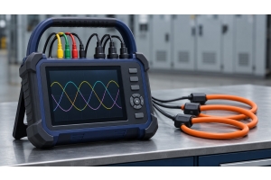
Are you facing communication system issues in your machinery, or unable to find the cause of erroneous data transmission in the communication network? SCMA is ready to present a complete solution with measurement tools and integrated signal transmission and reception devices to help solve the problem precisely. This article will help you understand the working principles, types, maintenance, as well as professional techniques for using a CAN Bus Analyzer.
What is a CAN Bus Analyzer?
A CAN Bus Analyzer is a hardware device that works with processing software to perform functions such as measuring, monitoring, recording, and analyzing communication signals in the Controller Area Network system. This device is designed to help engineers and technicians check the accuracy of data and identify electrical signal errors between control boxes. This type of tool is a crucial component in testing and maintaining the communication systems of vehicles, electric cars, as well as modern industrial automation systems.
How the CAN Bus Analyzer Works
The operation of the network communication analyzer is divided into clear main steps, allowing users to accurately observe the behavior of data on the bus. The CAN Bus data analyzer works through an internal processing system to convert the voltage levels in the signal line into digital data that can be easily analyzed further.
Signal Reception
The device connects directly to the CAN High and CAN Low signal lines of the system. The hardware detects the voltage difference between the Dominant and Recessive states on the communication line. Then the system accurately converts the voltage levels into digital data in the form of Logic 0 and 1.
Protocol Decoding
The software is responsible for separating the structure of the data frame, or CAN Frame, into different parts such as Identifier and Data Field. The system reads the ID value to clearly identify which device the data packet comes from and where it is being sent. All results are then decoded through protocol decoding to be displayed on the software screen for immediate reading and understanding.
Error Detection
The device has a system for checking the integrity of data packets using the Cyclic Redundancy Check or CRC principle. When the system detects EMI interference or a node in the system has failed, the device will immediately issue an Error Frame alert. This function helps engineers quickly and accurately locate communication failure points.
How many types of CAN Bus Analyzer are there?
This type of network analysis device comes in various forms to suit different testing tasks and environments. Choosing the correct type of CAN Bus Analyzer will greatly improve work efficiency and significantly reduce system checking time.
USB Interface (PC-based) Type
This is the most popular type for use in laboratories and general inspection tasks. The device connects the CAN signal line to a computer through a USB port to work with PC-based analysis software, allowing users to conveniently capture data, view real-time status, and send simulated commands.
Standalone / Data Logger Type
This type of device is designed as an independent data logging unit that does not need to be connected to a computer all the time. The device has an SD card slot or built-in memory to store bus traffic history. It is especially suitable for field testing, long-term data logging, or installation together with mobile machinery PLC systems.
Ethernet / Wi-Fi Network Type
This analysis device supports connection through a local area network (LAN) or wireless network (Wi-Fi) signal, allowing engineers to conveniently send remote analysis data to industrial parks or factory IoT systems. It meets the needs of machine inspection that is difficult to access the machine body while in operation.
Multi-Channel Analyzer Type
A high-level analysis tool with multiple signal channels within the same device, such as 2, 4, or 8 Channels. It supports monitoring and comparing data from multiple CAN networks simultaneously at the same time, making cross-network data transmission analysis (Gateway) more convenient and efficient.
CAN Bus Analyzer Maintenance
Proper maintenance of measuring instruments is essential for extending their lifespan and maintaining their accuracy. Proper maintenance of the CAN network analyzer will help reduce the risk of hardware and software failure during operation.
Hardware Maintenance
Users should regularly inspect connectors such as DB9, OBD-II, or Terminal Blocks to ensure there are no cracks, breaks, or rust. Clean the ports with compressed air and avoid using any corrosive chemicals. Store the device in a dry, impact-resistant box, protect it from moisture, and be cautious of static electricity (ESD) when handling the device.
Software and Firmware Maintenance
Regularly update the device's analysis software and firmware to the latest versions as recommended by the manufacturer. Systematically store and back up configuration files and important log files. Check the compatibility of drivers on the computer every time there is a new operating system update.
Device Integrity Inspection
Frequently test the device's data transmission using a Loopback test with a preliminary signal simulation board. Regularly inspect and calibrate the accuracy of the bus baud rate according to the scheduled time intervals. Regular integrity checks ensure that the tool is always ready for accurate measurements.

Application of CAN Bus Analyzer in Industry
This tool is widely applied in various industrial sectors that use CAN communication. The benefit of the CAN Bus analyzer in the manufacturing sector is helping the communication system between controllers and sensors to operate stably.
Analysis and Troubleshooting
Helps effectively detect errors occurring on the machine communication network. Engineers can use it to identify the causes of signal interference, data collisions, or Error Frames in the system, allowing machine malfunctions to be resolved correctly and quickly.

Real-time Monitoring
Used for monitoring the status of data transmission between various devices within the real-time control system. It helps clearly see the operation of sensors, ECU control boxes, or signal distribution modules, enabling system operators to immediately assess the performance of the machine.

Simulation & Testing
The device can act as a node to send test signals to other devices in the system. This helps the development team test the response of new devices before actually installing them on the production line, reducing risks and potential errors that may occur in the main control system.
Long-term Data Logging
Records all the data traffic history occurring in the communication system into memory. The recorded data can be replayed or analyzed in reverse to find the cause of randomly occurring problems. For more in-depth information about communication principles, visit CAN Bus Protocol Manual
Advantages of CAN Bus Analyzer
Introducing network analysis devices into an organization provides maximum benefits in terms of both time and work quality. The features of the CAN Bus Analyzer elevate the standards of maintenance and development of electronic systems across all industries.
Quick Error Detection
Helps users accurately identify the location and cause of problems in the communication system without guessing. Analyzes bus faults precisely, enabling the problem-solving process to be done quickly.
View Real-Time Data
Supports simultaneous display of communication data from all devices on the network in real time. Helps clearly see the overall communication structure and signal abnormalities.
Record Data for Analysis
Has a function to record past bus traffic data for studying system behavior patterns. Helps systematically analyze long-term or intermittent problems.
Reduce Repair Time
Eliminates the need to check each wire individually by viewing error codes through analysis software. Helps repair teams immediately locate damaged areas, greatly reducing machine downtime.
Supports Testing and Development
An essential tool for R&D engineers to test new electronic control boxes. Helps smoothly tune control systems and check device compatibility.
How to Choose a CAN Bus Analyzer
Selecting a communication network analysis device that is cost-effective and meets your needs requires considering several technical factors together.
- Protocol Standard Support: Check whether the device supports the CAN 2.0A/B standard or newer high-speed standards such as CAN FD.
- Number of Channels (Channels): Choose a 1-port model for general use, or a model with 2 ports or more if cross-bus data analysis is required.
- Galvanic Isolation System: Choose a model with an isolation system to prevent damage from power surges to the computer.
- Software Completeness: Consider software that is easy to use and supports DBC file conversion and detailed data logging.
- Operating System Support: Check whether the device driver supports the operating system in use, such as Windows or Linux.
Preparation Checklist for Using CAN Bus Analyzer
Before using the signal analyzer device, the operator should check the device and system readiness to ensure safe operation.
- Check cables and connectors: Inspect the DB9 connector or extension cable to ensure they are in good condition, with no broken wires or bent pins.
- Install drivers and software: Install the latest version of the data analysis software on the computer before connecting the device.
- Check resistance connection: Ensure that termination resistors of 120 ohms are connected at both ends of the bus system.
- Set Baud Rate to match: Set the data transmission speed on the software to match the actual communication speed of the system.
- Check Ground wire: Connect the ground wire to prevent voltage differences between devices, which may affect signal accuracy.
Summary
CAN Bus Analyzer is a necessary measuring and analyzing tool for inspection, troubleshooting, and development of communication systems in CAN Bus networks. Choosing a standard device with proper maintenance will help improve accuracy and effectively reduce downtime in industrial operations. For those looking for a high-quality analyzer, you can view the product details and all SCMA products immediately.
Interested in purchasing or consulting via LINE Official: @SCMA
If you want to buy CAN Bus Analyzer, you can purchase it from SCMA today!
SCMA has been a leader in the distribution of measuring instruments, test equipment, and automation systems for the industrial sector for many years. We have a team of expert engineers ready to provide advice and recommend the appropriate use of CAN Bus Analyzer for your specific type of work. Interested in product details and special offers? Contact us through our services to elevate your production process starting today.
Frequently Asked Questions
Can the CAN Bus Analyzer be used with CAN FD?
Yes, if the device model specifies support for the CAN FD standard, it will be able to read data at higher speeds
Why is Galvanic Isolation required in the analyzer?
To isolate electrical circuits from each other, helping to prevent damage to the computer from voltage surges or ground loops in the factory
What is the importance of DBC files in analysis?
DBC files convert binary data codes from the bus into human-readable parameter values, such as speed or temperature
Can the analyzer be used to simulate data transmission instead of ECU?
Yes, most devices have a Transmit function that can create and send data frames to simulate an ECU box
What happens if the Baud Rate setting does not match the system?
The software will not be able to decode the data, and error frames may appear on the communication system, causing communication to be disrupted