Loop impedance values indicate whether the expected earth fault current is sufficient for protective devices to disconnect promptly. This article explains the difference between Zs and Ze, how to interpret values together with protective device data, and the limitations to consider when using results to assess an electrical system.
What is Loop Impedance?
Loop impedance is the impedance of the circuit path under consideration. For earth faults, Zs includes the path from the supply through the phase conductor to the fault point and back to the supply through the protective system. It is measured in ohms and combines the effects of resistance and reactance.
How Loop Impedance Works
Evaluating the impedance of an earth fault loop starts by identifying the path that the fault current will take back, then applying the result to the voltage and the tripping criteria of the protective device.
Path of Earth Fault Current
When a phase conductor comes into contact with a metal part connected to the protective system, the fault current returns to the supply along the earthed path. The path may go through the protective conductor or through the earth and soil depending on the system type. Therefore, Zs depends on the complete circuit path.
Test Current Release
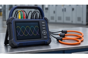
Some loop impedance testers (Loop Impedance Tester) use voltage changes during test current application to assess impedance. Direct measurement in live circuits should be performed only when necessary, following approved test plans and safety procedures.
Result Evaluation Calculation
The expected earth fault current can be estimated by dividing the phase-to-earth voltage by Zs, according to the conditions used for evaluation. Then compare it with the current that causes the protective device to trip within the specified time.
Zs, Ze and Phase-to-Neutral Impedance
The symbols depend on the path where Ze and Zs are measured. Ze and Zs are values used for earth fault loops, while the L–N impedance is used for the loop path between phase and neutral.
Earth Fault Loop Path (L–PE)
Measurement between phase and protective conductor at the test point is used to evaluate the impedance of the earth fault loop. The result depends on the type of earthing system and the parallel paths available.
Phase-to-Neutral Loop Impedance (L-N)
The L–N impedance considers the return path through the neutral conductor, and is therefore used to evaluate the expected short-circuit current between phase and neutral, and is separate from the Zs value which considers earth fault.
External Earth Fault Loop Impedance (Ze)
Ze is the impedance of the earth fault loop external to the installation at the source of the system under consideration. Use data from the electricity supplier or a measurement method suitable for the system and applicable requirements.
Total Impedance of Earth Fault Loop (Zs)
Zs is the total impedance from the supply to the fault point and back to the supply. For circuits where conditions are acceptable, Zs can be approximated as Zs ≈ Ze + (R1 + R2), where R1 is the resistance of the phase conductor and R2 is the resistance of the protective conductor of the circuit. Temperature and the effect of parallel paths should be considered when comparing with actual measured values.
Factors That Cause Changes in Loop Impedance
Maintaining the electrical system with low resistance is important to ensure that the emergency power-off devices will operate immediately in case of an emergency in the industrial factory.
Check the Tightness of Connections
The maintenance team must regularly tighten the nuts at the wire terminal and grounding connections in the control cabinet. Allowing contact points to become loose will cause the impedance value to increase, leading to accumulated heat.
Remove Rust and Corrosion
Moisture in the factory can easily cause rust stains. Technicians must regularly clean the grounding terminals or earth stakes. Allowing dirt to accumulate will obstruct the path of leakage current.
Inspect According to the Testing Plan and System Requirements
Determine the inspection items and intervals based on applicable requirements, environmental conditions, system modifications, and inspection history. Choose a testing method that isolates the power source when possible, and limit measurements during live conditions only when necessary according to approved methods. See the electricity measuring and analyzing instruments group of SCMA for system inspection work.
Record Results to Assess Risks
Compiling annual measurement records helps factory managers observe system changes. If abnormal increases in resistance values are found, the team can promptly plan corrective actions.
Application of Loop Impedance in Industry
In manufacturing, controlling loop resistance to meet standards is the most fundamental basis for electrical safety management within the factory.
Ensure Maximum Safety
Loop measurement results help assess automatic circuit disconnection when a ground fault occurs. These should be read together with continuity test results, grounding test results, and other system test items.
Prevent Electric Shock and Fire
When a ground fault occurs, appropriate impedance helps the fault current reach a level at which the protective device can disconnect the circuit within the specified time. This evaluation is part of reducing the impact of a fault.
Test the System Before Starting the Production Process
System acceptance starts with items that can be done while disconnecting the power source. The responsible person should assess whether loop measurement is required while energized or use Ze data and conductor test results according to the methods permitted by the regulations.
Analyze the Integrity of the Grounding System
If the Zs value is higher than expected, investigate the cause using circuit data, wiring connections, and protective conductor test results. For main earth resistance or conductor continuity, use specific test items.
Compare with Industrial Electrical Standards
Compare the Zs value and the specified disconnection time with the standards applicable to the location and type of system, including the manufacturer's protective equipment data.
What Can Loop Impedance Values Tell Us?
Knowing and checking the total resistance in the system provides enormous benefits for risk management. Investing in safety yields long-term value.
Assess Circuit Tripping Time During Faults
When Zs is low enough, the fault current may be high enough for the protective device to trip within the specified time. Compare this with the tripping characteristics of the installed device and the circuit criteria.
Enhance Employee Safety
Use loop results together with other tests to evaluate measures against electric shock and plan corrective actions when out-of-limit values are found.
Assess the Path Fault Current Will Flow
Test results help assess the total impedance of the fault path. Confirming the continuity of protective conductors requires separate continuity testing, as parallel paths may affect the Zs value obtained.
Discover Hidden Faults
Comparing results with original data helps identify areas to inspect, such as loose connections, corrosion, or differences between circuits that should be similar. Further inspection is needed to find the root cause.
Control Quality According to International Standards
Record the measurement results along with the method, location, protective devices, and on-site conditions, so that it can be reviewed to determine which criteria were used and which circuits need correction.
How to Read Zs Values in Relation to Circuit Tripping Criteria
Before judging the result, identify the circuit and type of earthing system, as well as the type, rating, and tripping time specified for the protective device of that circuit.
Check the source of the Zs value, specifying whether it comes from direct measurement or is estimated from Ze and conductor test results according to permitted methods.
Use criteria from the standard applicable to the system and the manufacturer's device data, considering the rating, tripping curve, and voltage used for evaluation.
Consider the effects of temperature, connection conditions, and parallel paths when comparing measured values with expected or limiting values.
When using low current mode in circuits with RCDs, check the device limitations and circuit conditions, as some RCD types may affect the measured value.
Separate the verification of RCD tripping time and the continuity of protective conductors into specific test items, and record the results and causes when values are out of limits.
SCMA Recommended Loop Impedance Measurement Tool Service
Having a good tool is just the beginning. Having a partner ready to assist is the heart of sustainable success SCMA Co., Ltd. has a solution for you
High-quality selected technology: We offer the Loop Impedance Tester Model 4118A and other models from reliable global brands
Integrated technical expertise: We have an engineering team ready to provide consultation, design systems, and quickly analyze on-site problems
Service center near you: We have offices covering the EEC industrial area and the northern region to ensure smooth electrical system maintenance for you
Summary
Zs is used to evaluate circuit interruption when a ground fault occurs, while Ze is the impedance of the external installation. The reading must know the measurement route, type of protective equipment, and disconnection time criteria, along with considering the limitations of the measurement method
Interested in purchasing or consulting via LINE Official: @SCMA
Consult SCMA on Choosing a Loop Impedance Measurement Tool
If you need to select a tool for measuring loop impedance, please inform the team SCMA about the type of system, circuit rating, and test list to choose the appropriate measurement range, test mode, and safety rating for the job
Frequently Asked Questions
What is Zs?
Zs is the total impedance of the fault loop at the point under consideration. It is used together with voltage and protective device characteristics to evaluate fault current and tripping time.
What is the No-Trip mode used for?
This mode reduces the likelihood of the RCD tripping during loop testing under conditions that the device supports. The original leakage current and RCD characteristics may still affect tripping and the readings obtained. Test the RCD tripping time separately using the specified method.
What is PSC calculation?
PSC is the expected short circuit current between the conductors under consideration. It is evaluated from the voltage and impedance of the path, to compare with the current breaking capability of the device. The expected earth fault current is called PEFC.
How often should the earthing system be tested?
The testing cycle depends on the applicable requirements, building type, usage conditions, inspection history, and system changes. The responsible party should define the inspection plan for the location.
Does SCMA offer after-sales service?
We have an integrated technical service ecosystem covering maintenance, calibration, and support from expert engineers.
References
Megger – Measuring Earth Fault Loop Impedance
Megger – Effect of RCD on Measured Values in Low Current Mode
IET – Questions on Inspection and Testing According to BS 7671
IET – Guidelines for Reducing Unnecessary Testing While Live