
In the world of industry and electrical engineering, safety is the most crucial aspect. An efficient grounding system (Grounding System) is the first line of defense against hazards from electrical shorts or leakage currents. The question arises: How can we ensure the effectiveness of a grounding system? The answer lies in an Earth Tester, also known as a ground resistance meter and soil resistivity tester. This article by the SCMA expert team delves into understanding this measuring tool thoroughly to help you confidently manage the safety of your electrical systems.
What is an Earth Tester?

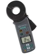
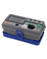
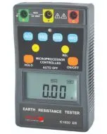
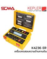
An Earth Tester is a specialized electrical measuring instrument designed to test and evaluate the resistance of soil in areas where grounding systems are installed. The key principle involves checking whether the installed grounding system can safely and quickly channel abnormal currents, such as leakage or lightning strikes, into the ground. If the measured value from the meter shows low resistance, it indicates that the grounding system is effective and allows current to flow easily into the earth. However, if the value is high, it suggests there may be issues with the grounding system and its ability to prevent hazards.
How to Use a Ground Resistance Meter
Based on the experience of the SCMA engineering team, obtaining accurate results from ground testing requires following proper and safe procedures. Although methods may vary depending on the model of the equipment, the general principles for using a soil tester are as follows:
- Prepare the area and equipment: Ensure that the instrument and measuring leads are in good working condition. Disconnect the grounding point to be tested from the electrical system for maximum safety.
- Install auxiliary earth rods (Auxiliary Earth Rods): Insert two metal rods, namely the voltage reference rod (P) and current return rod (C), into the ground at a distance from the grounding point to be tested (E) as recommended in the manufacturer's manual.
- Connect measuring leads: Connect the measuring leads correctly from the instrument to all three points. Typically, green wires are used for the grounding point (E), yellow wires for the voltage reference rod (P), and red wires for the current return rod (C).
- Measure and record results: Turn on the Earth Tester and start testing according to the steps of that particular model. Then document the measured resistance values for comparison with safety standard values.
- Verify accuracy: For precision, move the positions of the auxiliary earth rods (P) and (C), then retake measurements to confirm that the obtained values are stable and reliable.
Factors to Consider When Selecting an Earth Resistance Tester

Selecting the appropriate earth resistance tester is crucial for obtaining reliable and job-specific measurement results. The SCMA engineering team recommends considering the following factors:
- Measurement Range and Accuracy: Choose a device with an appropriate range (Range) and accuracy (Accuracy) that meets the required standards.
- Functionality: Consider necessary additional functions, such as stakeless measurement capability for areas difficult to install metal stakes or signal filtering functions.
- Durability and Protection Standards: The device should have dust and water protection ratings (IP Rating) suitable for field use to ensure durability.
- Data Management: Select a model with internal memory or the ability to connect to a computer for data transfer, which helps reduce errors in record keeping.
- Certification and Calibration: The tool should come with a calibration certificate (Calibration Certificate) from the manufacturer, and it is advisable to purchase from a reputable distributor with clear after-sales service.
Applications of Earth Resistance Meters
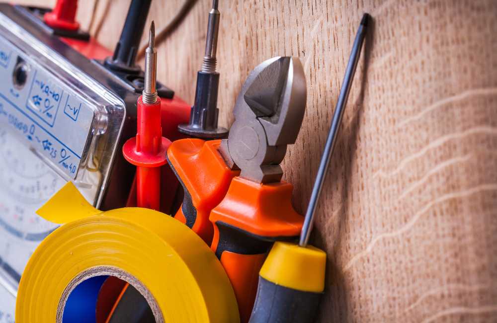
An earth resistance tester is a crucial tool for ensuring the safety of electrical systems in industrial plants and various buildings. It can be applied in numerous scenarios.
For Electrical System Inspection
It is used to regularly inspect installed electrical systems to ensure that the ground system's resistance remains within the safety standard and has not deteriorated over time.
During Electrical Equipment Installation
In the installation phase of new systems or machinery, performing a Ground Test is essential to confirm that the installed grounding system is correct and efficient before actual use begins.
Maintenance of Electrical Systems
This is part of preventive maintenance plans (Preventive Maintenance) aimed at detecting potential issues with ground systems such as corrosion or loose connections.
To Prevent Accidents
Having a low earth resistance value that meets the standard is a critical guarantee to prevent electrical shock hazards or damage to equipment caused by leaking current.
What Factors Affect Soil Resistance?
The soil resistance is not a constant value but can change according to various environmental factors. Understanding these factors will help engineers analyze measurement results more accurately.
Soil Moisture
Moist soil conducts electricity better than dry soil, resulting in lower resistance values. During the dry season, soil resistance may increase significantly beyond normal levels.
Type of Soil
The type of soil directly affects electrical conductivity; clay soils typically have lower resistance compared to sandy or gravelly soils, which is a factor that must be considered during grounding system design.
Surrounding Environment
Other underground structures such as metal pipes or building foundations can affect measurements. This makes the positioning of supplementary ground stakes crucial.
Density of Soil
Compacted soil conducts electricity better than loose soil, due to denser particle contact which facilitates easier electrical current flow.
Temperature
Temperature affects resistance values, especially in areas where temperatures are below freezing point. Water in the soil turns into ice acting as an insulator, causing a significant increase in resistance.
Why Use Soil Resistance Meters?
Safety is non-negotiable; electrical accidents often result from leakage currents flowing to equipment frames and grounding systems not functioning properly. High soil resistance values above standard levels (generally set at no more than 5 ohms) are the main cause of poor current flow into the ground. Using a soil resistance meter is the only scientific way to confirm that our safety measures are effective, making it the most worthwhile investment for life and property security.
If You're Looking for "High-Quality Soil Resistance Meters," Think SCMA!
Selecting an appropriate and high-quality soil resistance meter is the first step towards reliable safety. At SCMA, we are more than just a measuring tool supplier; we are your "technical partner." We curate Earth Testers from internationally recognized brands and have a team of expert engineers ready to consult you for tools that precisely meet your needs and budget. Because we believe accurate measurements start with reliable instruments.
Summary
The Earth Tester is not just a measuring tool, but an essential device that confirms the safety of the entire electrical system, from installation to maintenance and annual inspections. Understanding how to use it, selecting the right one, and factors affecting measurements will help engineers and system managers professionally prevent potential risks. If you need further advice or are looking for comprehensive measurement solutions, the SCMA team is always ready to support you.
Frequently Asked Questions
What is Earth Resistance?
Earth resistance refers to the value indicating the soil's ability to resist electrical current flow. The lower this value, the better, as it means that abnormal currents can quickly and safely dissipate into the ground.
What is an Earth Tester?
An instrument used to measure the specific resistance of the soil to evaluate the performance of the grounding system (Grounding System), ensuring that the electrical protection system operates efficiently.
How do you use an Earth Tester?
In general, it involves using two additional metal stakes inserted into the ground along with the stake being tested. The instrument then applies current and measures the voltage generated to calculate earth resistance in ohms (Ω).
Why is an Earth Tester important?
Because it is the only tool that can confirm whether your grounding system meets safety standards, preventing electrical shock hazards, equipment damage, and ensuring personnel and plant safety.