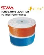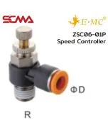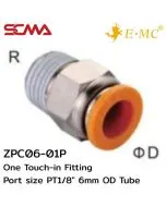
Pneumatic systems are the heart of machinery operation. When parts deteriorate to the point where rubber seals leak or cylinders jerk, it causes misalignment and disrupts production lines SCMA is ready to help you solve problems with pneumatic equipment and pneumatic circuits that match your model exactly. We offer online spare parts ordering services for pneumatic components, which are convenient and fast. Our engineering team provides free thread comparison and expedited shipping so mechanics can use them immediately.
What is a Pneumatic System? Why it's the Heart of Automation Systems
To clarify basic terminology for maintenance technicians and procurement departments, a pneumatic system is technology that uses compressed air as mechanical energy to drive machinery. In summary, these components function like the muscles of robotic arms, handling tasks such as pushing, pulling, lifting, or gripping workpieces in automated production lines. The mechanisms operate quickly and accurately respond to commands from PLC cabinets; modern automation systems cannot do without this system.
Delve into the Meaning: A Pneumatic System Means Engineering Control of Flow
If we delve deeper into the engineering definition, a pneumatic system means controlling pressure and direction of compressed air flow through directional control valves. In designing a good pneumatic circuit, one must always consider pressure drop (Pressure Drop) in the piping system. Engineers must select pipe sizes and fittings that match the total air consumption of machinery; neglecting this can lead to insufficient end-of-line pressure, causing cylinders to lack the force needed to push parts as specified.
How does a pneumatic system work and how is it different from hydraulic?
The most obvious difference is that pneumatic systems use air as the medium of operation, providing high-speed movement, cleanliness, and safety from oil contamination. Pneumatic systems are therefore suitable for electronic assembly or food production factories. On the other hand, hydraulic systems use oil as the primary driving force, capable of generating immense pressure but with slower movement. Hydraulic systems are designed to handle heavy-duty work such as metal stamping presses that require high stability in pressing cycles.
Structure and Main Components of an On-site Pneumatics System
Understanding the components of a pneumatics system on machinery helps technicians diagnose problems accurately. The entire system works in tandem from start to finish.
FRL Unit (Filter Regulator Lubricator)
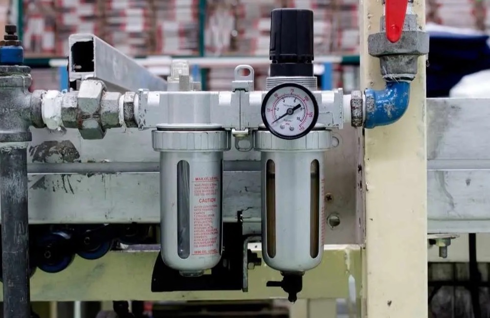
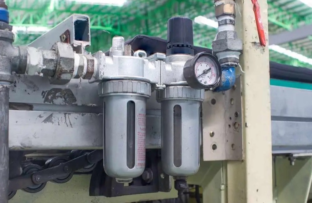
The first component of a pneumatic system starts with the filter regulator lubricator (FRL unit). This equipment captures water, dust particles, and oil droplets before compressed air enters machinery. Maintaining air quality is crucial; maintenance staff must regularly drain water or replace filters according to cycles. Clean air significantly extends the lifespan of seals within other pneumatic components.
Directional Control Valve
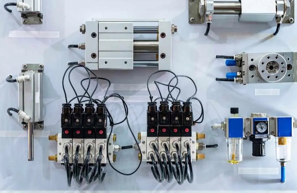
The filtered compressed air then flows to the solenoid valve, which receives electrical signals from the control panel to switch the direction of airflow in the pneumatic circuit. The operation of the valve determines whether compressed air pushes the cylinder rod out or pulls it back. Technicians must choose a port size that matches the required volume of air; selecting a valve that is too small will cause insufficient air flow, resulting in slower machine performance.
Actuator (End-effector)
This is where pneumatic energy is converted into mechanical movement. Components in a pneumatics system include cylinders, air motors, and workpiece grippers. Cylinders directly act upon the workpieces with force; engineers must calculate the pushing force (Force) to match the weight of the on-site load. Using undersized cylinders for heavy loads can cause internal seals to rupture and leak, necessitating premature maintenance.
Tubing & Fitting
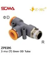
The tubing system is akin to blood vessels that transport energy throughout the pneumatic circuit. Choosing pneumatic tubing (PU or Nylon) requires considering its pressure and temperature resistance capabilities on-site. Quick-connect fittings connect all components together. On-site technicians must cut tubing at a right angle before inserting it into connectors; angled cuts are often the primary cause of air leaks, leading to wasted factory energy.
Current Industrial Applications of Pneumatic Systems
The industrial pneumatic systems have advanced significantly, perfectly accommodating the complexities of modern production lines. Let's take a look at some real-world applications.
Packaging System
Packaging machinery requires high speed and precise timing. Pneumatic systems are used to drive mechanisms such as box folding, bag sealing, and product labeling. High-speed cylinders work seamlessly with position detection sensors, maintaining a consistent cycle time that helps achieve production targets. Factories can efficiently reduce waste from improperly sealed bags or labels coming off.
Belt Sorting System
In distribution centers or large production lines, sorting products is crucial. Air systems control cylinders to kick items into boxes or slide them along separate tracks based on type. Solenoid valves respond instantly to commands from vision sensors, a speed that hydraulic systems cannot match. This makes the pneumatics system dominate the logistics market.
Vacuum Handling for Delicate Parts
Picking up glass sheets, PCB panels, and small electronic components requires the application of industrial pneumatic systems in conjunction with vacuum generators (Vacuum Ejector). Vacuum heads gently lift parts without damaging them. Using suction instead of mechanical grippers prevents scratches and breakage during inter-station movement.
Automated Assembly Work
Automated machinery used for automotive part assembly relies heavily on pneumatic mechanisms. Slide cylinders or rotary actuators feed parts into joining or screwing stations. Precise air pressure control ensures proper fitting without excessive force that could deform the parts. Engineers can adjust cylinder speeds to work smoothly with robotic arms.
Air System Leaks and Inspection Techniques on Machinery
The faint hissing sound of air leaks at the joints of the air system is a major cause of high energy costs in factories. Technicians must have proper techniques to locate leaks effectively.
- Air system leaks usually occur at the ends of bent air lines or where field workers cut air lines without squaring them before connecting to quick couplings.
- Maintenance technicians should frequently inspect the internal locking teeth (Fitting) for wear from frequent insertion and removal. If worn, replace parts immediately.
- The rubber seal around the pneumatic cylinder shaft may tear due to friction with external dust particles, causing compressed air to leak across chambers, leaving no pulling force on workpieces.
- Internal gaskets in solenoid valve sets can harden from accumulated heat near machinery, leading to constant air leaks through exhaust ports.
- Setting the incoming air pressure (Pressure) too high above what pneumatic equipment specifications allow will cause joints to crack and air lines to burst off locking sets.
- The maintenance team should spray soapy water at all copper-threaded connection points. If bubbles appear, it indicates insufficient tape wrapping; re-wrap tightly.
Preventive Maintenance Standards for Pneumatic Systems
Predictive maintenance of pneumatic equipment extends the lifespan of machinery and reduces the risk of sudden production line breakdowns. Technicians should plan their work carefully.
- Schedule regular checks of the pneumatic system. Mechanics must drain water from air filter cups regularly to prevent moisture droplets from entering and damaging lubricants inside valves.
- Check the alignment of cylinder shafts. Misalignment during installation can create side forces, causing seals in cylinders to wear out much faster than their actual lifespan.
- Replace FRL Unit air filters immediately if they become dark or have thick oil residue buildup. Clogged filters cause downstream pressure drop (Pressure Drop) issues.
- Inspect the condition of PU hoses in pneumatic circuits. If hoses start to harden or darken, replace them throughout the system to prevent hose breakage during high-speed operation.
- Check the tightness of cylinder mounting bolts and control valve nuts. Continuous vibration from operations can cause bolts to loosen, shifting mechanical positions.
- Record the operational life of each solenoid valve. When nearing the maximum cycle time specified by the manufacturer, plan ahead for spare part orders.
Summary
In summary, pneumatic systems, or air systems, are the heart of industrial machinery. Understanding what pneumatics is and maintaining them properly helps reduce downtime sustainably. If your pneumatic equipment is nearing the end of its lifespan, SCMA offers high-quality pneumatic spare parts for service. Our team provides free online specification comparisons and fast delivery so you can repair machinery immediately.
If you want to buy, you can purchase from SCMA today!
SCMA offers the highest convenience for maintenance customers. You can take a picture of the Nameplate of the original pneumatic system part or specify your requirements and send it directly to our website here. Our support engineering team is ready to match the model of high-quality replacement brand pneumatics, check screw sizes for free, and deliver pneumatic products quickly nationwide. Mechanics can install them perfectly on machines, reducing on-site work complications.
Frequently Asked Questions (FAQ) About Pneumatic System Usage
Q1: What is a pneumatic system? Can it use liquid instead of compressed air?
A: To clarify, a pneumatic system is designed to use only compressed air. It's not possible to substitute water or oil into the valves or cylinders of a pneumatic system. Liquids would cause rubber seals inside to swell and leak, creating rust that can destroy equipment immediately.
Q2: The cylinder in the pneumatic system is jerking. Adjusting the speed controller doesn't help. Where should I look for a solution?
A: Have the technician remove the load (workpiece) first and try operating it empty. If the cylinder in the pneumatic system still jerks, this indicates that the internal lubricating grease has dried up or there is friction between the piston and cylinder sleeve. The technician must disassemble the pneumatic parts to replace a new set of seals (Seal Kit).
Q3: Can pneumatic equipment be used in high-temperature areas like ovens?
A: Standard pneumatic equipment can withstand temperatures around 60-70 degrees Celsius. If the installation area of a industrial pneumatic system has accumulated heat, engineers must order special specifications that change internal seals to Viton material which can withstand up to 150 degrees Celsius.
Q4: How do you find leaks (Air Leak) in the air line sub-systems before machinery?
A: The classic method used by pneumatic maintenance technicians is listening for hissing sounds or using soap bubbles to check fittings. Nowadays, large factories prefer to use high-frequency wave detectors (Ultrasonic Leak Detector) to pinpoint small leaks in the air system that human ears cannot hear.
Q5: Can I consult about wiring when purchasing pneumatic system parts online with SCMA?
A: Yes, consultations are free. The Technical Support team at SCMA consists of real engineers who know what a pneumatic system is all about. We help you read valve symbols, advise on air line routing (Piping) for the pneumatic circuit and wiring electrical connections to PLC cabinets. You can be sure that once you buy parts from us, they will work perfectly.