
SPECIAL PROMOTION — Up to 40% off across many product groups, until 31 December 2026 · Click to see all promotion itemsIFM, Sensor, Automation SystemMeasuring / Testing InstrumentsTemp Indicator, Control, T/C, RTD, TimerHeater, SCR Control, Solid State, Power Supply, Control CabinetField Measuring Instruments, Pressure Gauge, Level Control, Flow MeasurementEMC, Pneumatic, Solenoid ValveInspection Test Lamp, Head Light, Automotive Measuring InstrumentWeighing Scales, Marking Machine, PrintersEducational Training SystemsHot Line Tools & Equipment SPECIAL PROMOTION — Up to 40% off across many product groups, until 31 December 2026 · Click to see all promotion itemsIFM, Sensor, Automation SystemMeasuring / Testing InstrumentsTemp Indicator, Control, T/C, RTD, TimerHeater, SCR Control, Solid State, Power Supply, Control CabinetField Measuring Instruments, Pressure Gauge, Level Control, Flow MeasurementEMC, Pneumatic, Solenoid ValveInspection Test Lamp, Head Light, Automotive Measuring InstrumentWeighing Scales, Marking Machine, PrintersEducational Training SystemsHot Line Tools & Equipment View promotion items View all
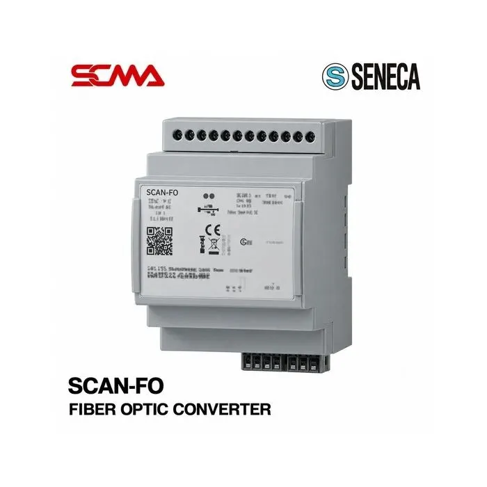
SCAN-FO FIBER OPTIC CONVERTER SENECA
Price on request – please contact us
Out of stock
SKU
050960
Out of stock

SCAN-FO, SENECA, Fiber Optic Converter, CAN to Fiber Optic Converter, CAN-Bus Fiber Converter, CAN Bus to Optical Fiber, CANopen Fiber Optic Converter, CAN 2.0, CANopen, Industrial CAN Converter, Optical Communication Converter, Fiber Optic Communication, Single Mode Fiber Optic, Multimode Fiber Optic, Single Loop, Double Loop, 4kV Isolation, DIN Rail Converter, Industrial Communication, CAN Network Extension, PLC Communication, Industrial Automation, Smart Factory, Fiber Optic Signal Converter, CAN-Bus to Fiber Optic Converter, CAN to Fiber Optic Converter Device, CANopen Signal Converter, CAN Bus Converter Device, Optical Fiber Communication Equipment, Industrial Communication Converter, SENECA Signal Converter, CAN-Bus Communication Equipment, Industrial Communication System
*Price does not include VAT
Fiber Optic Converter SENECA SCAN-FO (CAN to Fiber Optic Converter)
SENECA SCAN-FO Fiber Optic Converter is a communication signal converter that transforms the CAN-Bus signal into an optical fiber signal for transmission and vice versa when used with compatible devices on the other end. It is suitable for automatic control systems and industrial communication networks using CAN-Bus.
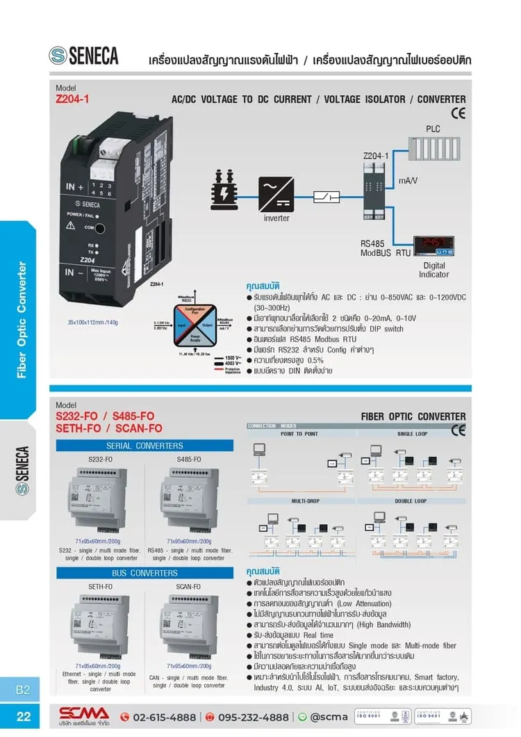
The SCAN-FO supports CAN 2.0 and CANopen communication protocols, maintaining the original CAN communication format during data transfer. It can be used with single-mode or multimode optical fiber cables as well as single-loop or double-loop connections depending on the selected model.
Using optical fibers reduces electromagnetic interference along the communication path and allows for connecting CAN-Bus devices in distant locations. This is ideal for machine control systems, industrial automation systems, and control networks that require data transmission via optical fiber.
General Features
- Brand: SENECA
- Model: SCAN-FO
- Product Type: CAN to Fiber Optic Converter
- CAN-Bus signal converted into optical fiber signal
- SUPPORTS CAN 2.0 and CANopen communication protocols
- 1 x CAN Communication Port
- SUPPORTS single-mode or multimode optical fibers depending on the model
- SUPPORTS single-loop or double-loop connections depending on the model
- 3-way electrical isolation system, 4 kV
- Status indicator lights for CAN communication, fiber optic communication, and device status
- Built-in diagnostics system
- Configurable via SENECA Compositor software
- Suitable for DIN Rail mounting
- Designed for industrial CAN-Bus communication systems
Technical Specifications (Technical Specifications)
| Brand | SENECA |
| Model | SCAN-FO |
| Product Type | CAN to Fiber Optic Converter |
| Communication Interface | 1 x CAN Port |
| Communication Protocol | CAN 2.0, CANopen |
Functionality
SENECA SCAN-FO receives communication data from the CAN-Bus network through the CAN port, then converts electrical signals into light signals to transmit via fiber optic cables to a signal converter on the other end. The receiving device will convert the light signals back into CAN signals to connect with devices in the remote network.
Transmitting data over optical fibers helps reduce electromagnetic interference along the communication path, making it suitable for systems with machinery, inverters, or high-power electrical equipment installed nearby.
The unit supports CAN 2.0 and CANopen communications; system configuration must match that of both the originating and receiving devices, as well as adhere to manufacturer guidelines for connection conditions and terminating a CAN-Bus line.
Sub-models and Connection Types
| SCAN-FO-MONO-SL | Single-mode Fiber / Single Loop |
| SCAN-FO-MONO-DL | Single-mode Fiber / Double Loop |
| SCAN-FO-MULTI-SL | Multimode Fiber / Single Loop |
| SCAN-FO-MULTI-DL | Multimode Fiber / Double Loop |
The MONO sub-model supports single-mode fiber, uses LC connectors and has a maximum communication distance of 10 kilometers. The MULTI sub-model supports multimode fiber with dimensions of 50/125 or 62.5/125 micrometers, uses ST/ST connectors, and has a maximum communication distance of 500 meters. Actual distances depend on the quality of the fiber optic cable, signal loss, and installation conditions.
Installation and Usage
- Check the sub-model code to select appropriate fiber types and loop configurations
- Install the unit onto a DIN rail within the control cabinet
- Connect the CAN port to the CAN-Bus device according to the manufacturer's wiring diagram
- Verify CAN-H, CAN-L connections and signal termination as per network requirements
- Connect fiber optic cables to the selected sub-model connectors
- Supply power 12-35 VDC or 8-24 VAC as specified
- Configure operation through SENECA Compositor software
- Check CAN and fiber optic communication status lights before use
- Ensure fiber type, signal distance, and network structure comply with requirements
Examples and Usage Guidelines
- Connects CAN-Bus networks between remote control cabinets
- Works with the CANopen system in machine control and industrial automation systems
- Applies to communication systems between control devices and CAN-Bus supported drives
- Used in measurement or remote control systems that require fiber optic communication
- Suitable for areas with electromagnetic interference that may affect copper wire communication
- Applied in Industrial Automation, Smart Factory, and CAN-Bus controlled systems
Considerations
- SCAN-FO is a CAN to Fiber Optic signal converter, not an RS232, RS485 or Ethernet Converter
- The MONO or MULTI version must be selected according to the fiber type and connector
- The SL or DL version must be chosen based on the network structure
- Maximum communication distance is 10 km or 500 m depending on sub-model and actual installation conditions
- Check CAN 2.0 or CANopen system compatibility with end devices before installation
- Verify supported CAN communication speed from the sub-model manual before installation
- Check power supply voltage and electrical connectors before powering up
- Ensure correct CAN wiring and termination resistor installation according to network diagram
- The SCAN-FO code alone cannot confirm fiber type, connector type, and Loop configuration of shipped products
- It is recommended to review the manufacturer's manual and sub-model documents before actual use
Write Your Own Review
This website uses cookies
We use cookies to make the site work properly, to understand how it is used, and to show content that is relevant to you. You choose which types to allow; strictly necessary cookies are always on. Privacy Policy
🤖 AI Assistant
Ask about products, specs and replacement models
Hello 👋 Ask us anything — find products, compare specs, or troubleshoot.
🗑 Clear history