
SPECIAL PROMOTION — Up to 40% off across many product groups, until 31 December 2026 · Click to see all promotion itemsIFM, Sensor, Automation SystemMeasuring / Testing InstrumentsTemp Indicator, Control, T/C, RTD, TimerHeater, SCR Control, Solid State, Power Supply, Control CabinetField Measuring Instruments, Pressure Gauge, Level Control, Flow MeasurementEMC, Pneumatic, Solenoid ValveInspection Test Lamp, Head Light, Automotive Measuring InstrumentWeighing Scales, Marking Machine, PrintersEducational Training SystemsHot Line Tools & Equipment SPECIAL PROMOTION — Up to 40% off across many product groups, until 31 December 2026 · Click to see all promotion itemsIFM, Sensor, Automation SystemMeasuring / Testing InstrumentsTemp Indicator, Control, T/C, RTD, TimerHeater, SCR Control, Solid State, Power Supply, Control CabinetField Measuring Instruments, Pressure Gauge, Level Control, Flow MeasurementEMC, Pneumatic, Solenoid ValveInspection Test Lamp, Head Light, Automotive Measuring InstrumentWeighing Scales, Marking Machine, PrintersEducational Training SystemsHot Line Tools & Equipment View promotion items View all
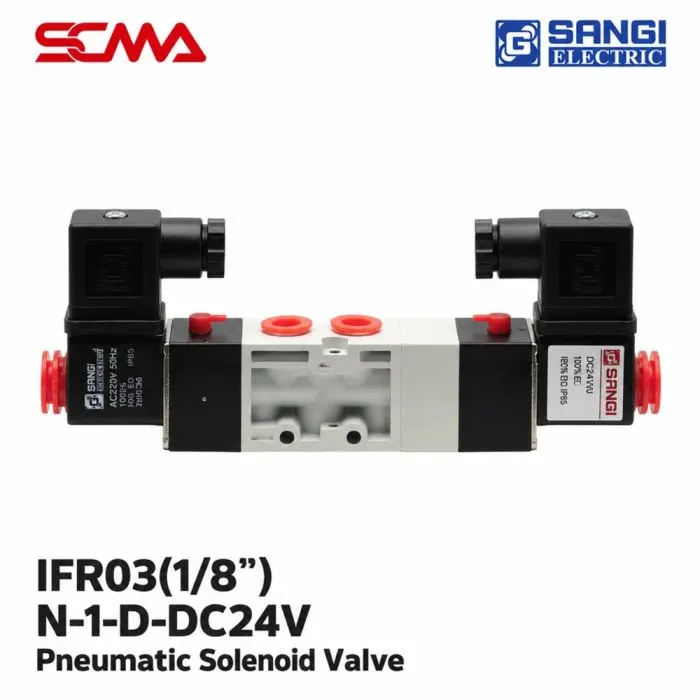
Solenoid Valve Model : IFR03(1/8")-N-1-D-DC24V / Pneumatic 5/ Plug LED
Special Price THB 4,425.00 Regular Price THB 5,900.00
In stock
SKU
040817
In stock: 10 pcs
Delivery within: 22/11/2026
🚚 Free delivery on orders of THB 2,500 or more! (standard delivery fee THB 100)

IFR03(1/8")-N-1-D-DC24V, SANGI, Pneumatic Solenoid Valve, IFR03 Series, FR03 Series, 5/3 Way, 5 Ports 3 Positions, 1/8 Inch, Double Coil, Dual Coil, DC24V, 24VDC Solenoid Valve, Plug LED, LED Indicator, Solenoid Valve with LED, Pneumatic Directional Control Valve, Air Control Valve, Industrial Solenoid Valve, Pneumatic Automation, Solenoid valve, solenoid valve, pneumatic solenoid valve, directional control valve, air control valve, 5/3 way solenoid valve, three position solenoid valve, dual coil solenoid valve, LED solenoid valve, 24VDC solenoid valve, 1/8 inch solenoid valve, cylinder control valve, industrial pneumatic equipment
*Price does not include VAT
SANGI IFR03(1/8")-N-1-D-DC24V 5/3 Way Pneumatic Solenoid Valve with Dual Coil and Plug LED
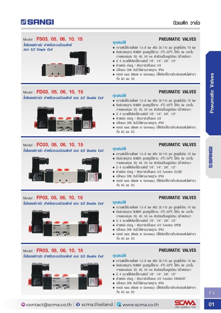
SANGI IFR03(1/8")-N-1-D-DC24V Pneumatic Solenoid Valve is a solenoid valve for pneumatic systems used to control the direction of compressed air flow. It references the FR03 series, which is a 5/3 Way or 5 Ports 3 Positions valve with five air channels and three positions.
This model specifies an air fitting size of 1/8 inch according to the model number, uses DC24V coil voltage, and comes with a plug that has a status indicator LED. The FR03 series uses dual coils (Double Coil) for controlling valve position direction changes, suitable for automatic machinery control systems and pneumatic equipment control.
General Features
- Product Model: IFR03(1/8")-N-1-D-DC24V
- Brand: SANGI
- Product Type: Pneumatic Solenoid Valve
- Product Series: IFR03
- Valve Reference FR03 Series: 5/3 Way (5 Ports, 3 Positions)
- Air Fitting Size: 1/8 inch
- Operating Medium: Air (compressed air) according to the FR03 series data
- Coil Configuration Reference FR03 Series: Double Coil
- Coil Voltage: DC24V
- Status Indicator Plug LED Included
- Suitable for compressed air direction control systems in automatic machinery
Technical Specifications (Technical Specifications)
| Model | IFR03(1/8")-N-1-D-DC24V |
| Brand | SANGI |
| Product Type | Pneumatic Solenoid Valve |
| Product Series | IFR03 |
| Valve Function | 5/3 Way (FR03 Series Reference) |
| Number of Ports | 5 (FR03 Series Reference) |
| Number of Positions | 3 (FR03 Series Reference) |
| Port Size | 1/8" |
| Operating Medium | Air |
| Coil Configuration | Double Coil (FR03 Series Reference) |
| Coil Voltage | 24VDC |
| LED Indicator | Plug LED |
Principle of Operation
The 5/3 Way Solenoid Valve has five air channels, including one supply channel, two working channels, and two exhaust channels. It has three operating positions to control the flow path of compressed air to pneumatic equipment.
The FR03 Double Coil model uses two sets of electrical coils to command valve position changes. Each coil controls a change in direction as specified. When there is no power supply command, the 5/3 Way valve generally returns to its center position using return mechanism. However, it's necessary to check the specific circuit symbol of the actual model before use.
The Plug LED is an electrical status indicator at the plug set that makes checking power delivery to the coil circuits more convenient. The LED light does not serve as a direct measurement or confirmation tool for mechanical valve position.
Size and Installation
IFR03(1/8")-N-1-D-DC24V specifies an air fitting size of 1/8 inch. It is important to check the thread standards and compatibility of fittings, as well as the positions of supply, working, and exhaust channels before installation.
The electrical circuit connection must use a DC24V power source and appropriate control devices for both coil sets. The plug set's LED light terminal wiring should be checked according to the manufacturer’s documentation before powering up.
Examples and Usage Guidelines
- Control two-way pneumatic cylinder movement direction
- Used in automatic machine compressed air directional control systems
- Applied with workpiece holding and moving systems using compressed air
- Work together with PLC or DC24V coil driver circuits that support dual-coil control
- Use Plug LED to check power delivery status to coils during installation and maintenance
Considerations
- The IFR03(1/8")-N-1-D-DC24V model specifies DC24V coil with Plug LED
- The 5/3 Way Double Coil configuration refers to the FR03 family in the catalog
Write Your Own Review
This website uses cookies
We use cookies to make the site work properly, to understand how it is used, and to show content that is relevant to you. You choose which types to allow; strictly necessary cookies are always on. Privacy Policy
🤖 AI Assistant
Ask about products, specs and replacement models
Hello 👋 Ask us anything — find products, compare specs, or troubleshoot.
🗑 Clear history