Directional Control Valve helps to solve classic on-site problems such as seal rupture or spool sticking, symptoms that cause the cylinder to malfunction and stop the machine (Downtime) immediately. Switching to high-quality directional valve and control valve helps stabilize the system. SCMA offers online services for engineers to review pneumatic circuits free of charge, preventing issues where purchased spare parts are incorrectly ported with air supply. Easy ordering, fast delivery to your factory.
What is a Valve? Why is the Directional Control Valve the Brain of Machinery?
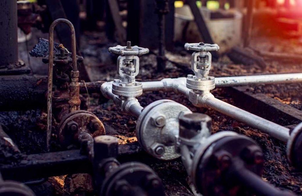
Recent technical graduates may wonder what a valve is. A basic explanation is that it's a mechanical device used to open, close, or throttle the flow path in a pipe system. When used in an Automation system, directional control valve acts like a brain issuing commands. This component determines the direction of compressed air or oil flow to actuators (Actuator) according to PLC instructions. Selecting an accurate directional control valve ensures that robotic arms or cylinders move in and out perfectly without any hitches.
In-depth Engineering Working Principle of Directional Control Valve
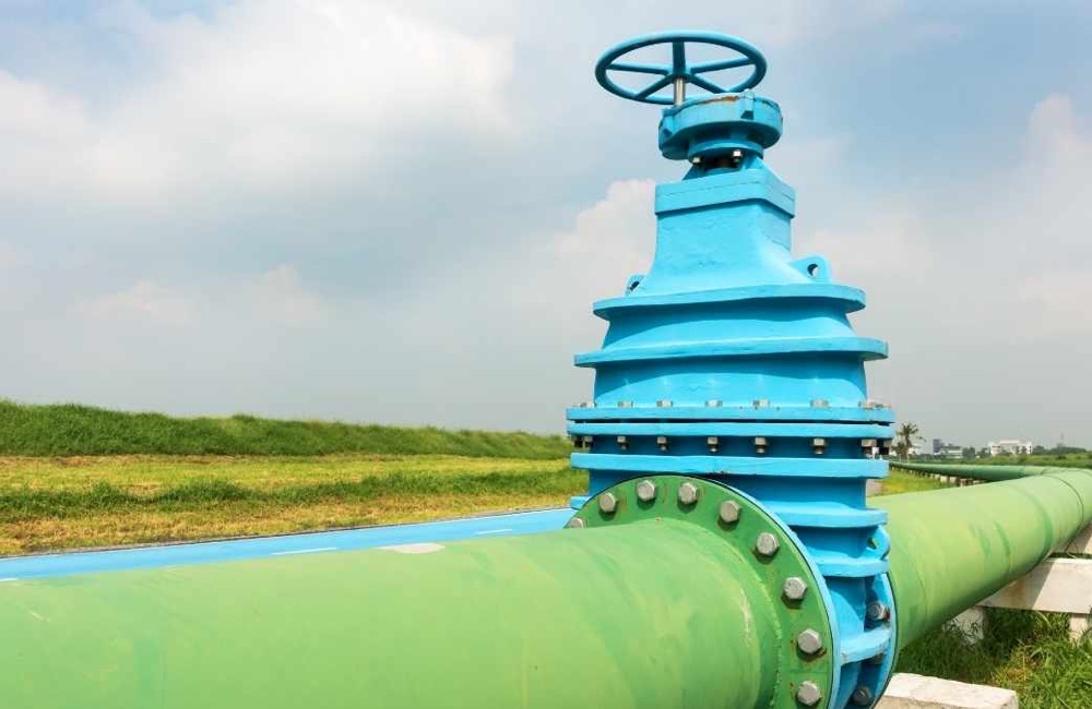
The shifting mechanism of the directional control valve occurs when the valve receives an external command signal. These signals may be manual pressing, pneumatic (Pneumatic Pilot), or electrical (Solenoid). Upon receiving the order, the internal spool mechanism slides inside the valve housing, facilitating compressed air to flow into one side of the cylinder. A standard control valve is designed to simultaneously vent the old port to atmosphere to reduce back pressure.
What is a Spool? A Crucial Component That Maintenance Technicians Must Care for Special Attention
A deep question that maintenance technicians must know the answer to is what is a spool? This component is a cylindrical shaft with left and right grooves, fitted inside the sleeve of the directional control valve. It slides back and forth to switch air channels. The main enemy of spools is dust or water droplets in the main pipe system, which can adhere to the spool shaft causing deep scratches that tear the O-ring seal. This is the primary cause of directional valve sticking or having a hissing air leak.
How to Read Directional Control Valve Symbols and Pneumatic Valve Symbols
Understanding engineering symbols helps maintenance teams order parts accurately.
The Meaning of Rectangles (Positions)
To read directional control valve symbols, start by understanding the rectangles. The number of adjacent squares indicates the number of working positions for that valve; two squares mean it has two operating positions (left-right). Technicians must interpret this symbol correctly before ordering parts.
Arses Indicate Air Flow Direction
The arrows within pneumatic valve symbols clearly indicate air flow direction. The arrowhead points to the direction of compressed air entering the cylinder, while a line with a cross (T) indicates that an air port is blocked. Engineers must follow the arrows to check if the directional control valve is delivering air at the right intervals.
Distinguishing Normally Open (NO) and Normally Closed (NC) Systems
Understanding pneumatic valve symbols helps technicians correctly choose between a normally open (NO) or normally closed (NC) system. The NC specification keeps air blocked until an activation signal is received, while the NO specification allows air to flow continuously. Choosing the wrong air directional control valve can cause the cylinder to operate in opposition to PLC commands immediately.
Differences Between Air Direction Control Valves and Hydraulic Direction Control Valves
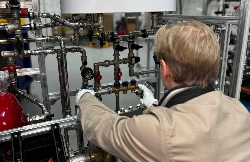
Compressed air systems and hydraulic systems have different strengths. The choice of equipment should be based on the requirements of the machinery.
Advantages of Air Direction Control Valves
Air direction control valves are used with compressed air from factory air compressors. This system provides high-speed movement, cleanliness, and safety. The valve structure is lightweight and easy for technicians to disassemble and assemble. The pneumatic system meets the needs of electronic component assembly that requires high cleanliness.
Advantages of Hydraulic Direction Control Valves
Hydraulic direction control valves are designed to withstand oil pressures in hundreds of bars, with thick cast iron structures that can handle heavy-duty work. This type of equipment is suitable for metal stamping machines that require enormous pressure. The internal mechanism of this directional valve uses oil as a lubricant.
The Application of Single-Direction Air Valves (Check Valve) in Safety Circuits
- Air check valves are small components but play a crucial role in automation systems.
- The mechanism is designed to allow compressed air to flow in one direction only, preventing the air from reversing back into the compressor or main valve.
- Engineers must incorporate air check valves with directional control valves when designing circuits.
- The installation together helps maintain residual pressure in vertical cylinders very well.
- This system prevents workpieces from falling and being damaged during power outages or sudden drops in factory air pressure.
Symptoms of Control Valve Sticking, Air Leakage, and Emergency On-Site Inspection Methods
- Immediate troubleshooting steps when a control valve fails to operate include checking the coil terminal signals first.
- If the PLC signal is normal, try pressing the Manual Override button at the end of the valve housing with a screwdriver.
- Pressing this button simulates the operation of the directional control valve without relying on electrical power.
- If the manual override does not work and the spool does not move, it indicates that the spool is stuck against the valve housing.
- The technician must disassemble to clean, replace a seal kit (Seal Kit), or immediately install a new directional valve.
Summary
Directional control valve or directional control valve is the brain that commands machinery to move accurately. Understanding what a valve is and maintaining the spool shaft properly will help reduce downtime issues if original parts deteriorate. If spare parts are worn out, SCMA is ready to provide specification-matched air directional control valve services online. We deliver the correct-specification control valve for you to use immediately.
If you want to purchase, SCMA is available today!
SCMA offers 100% online service strength. Customers simply take a photo of the old directional control valve, or sketch a rough pneumatic circuit diagram and send it to our Line OA. Our engineering team will read the directional control valve symbols, compare port thread sizes, check power supply voltage for free. We deliver directional valve quickly, ready for wiring and installation on your machinery.
Frequently Asked Questions (FAQ) About Directional Control Valve Usage
Q1: What are the differences between a 5/2 way and a 5/3 way valve? How should I choose?
A: A 5/2 way valve has two operating positions, used to command the hydraulic cylinder to move fully forward or backward. The directional control valve 5/3 way has an additional third position (middle position) which is used to command the cylinder to stop and hold in the middle stroke while moving.
Q2: Can a spool shaft be sanded with sandpaper for repair?
A: Absolutely not recommended. The spool shaft is precision-machined at micron levels; using sandpaper would distort its shape, causing the control valve to leak more air across ports than before. Replacement seals or a new unit are required.
Q3: Can hydraulic directional control valves be adapted for pneumatic systems?
A: No, it cannot be done. A hydraulic directional control valve is designed to use oil as lubrication for the spool; using it with dry air will cause mechanical binding and sticking immediately. The internal seal materials of directional control valves in both systems are chemically resistant to different substances.
Q4: If the pneumatic valve symbols on a label have faded away, how can I order new ones?
A: Customers can take full photos of the directional valve, along with specifying the type of cylinder (Single or Double Acting), and send them to SCMA via LINE. Our engineering team can decode the pneumatic valve symbols and match specifications for replacement valves free of charge.
Q5: When purchasing a directional valve online from SCMA, is coil specification matching service included?
A: SCMA provides comprehensive directional valve specification matching. Engineers will inquire about the control cabinet power supply (e.g., 24VDC or 220VAC) to ensure correct coil specifications are provided. The new pneumatic directional valve can be directly connected to existing wiring on machinery without risk of electrical shock.